
Self-boosting method with suppression of high lateral electric fields

a high-lateral electric field and self-boosting technology, applied in semiconductor devices, digital storage, instruments, etc., can solve the problems of worse disturbance of the characteristic of high-electric field enhanced programs, achieve high electrical field, suppress excessive boosting, and increase the number of word lines between the isolation cell and the selected word line

Active Publication Date: 2008-09-23
SANDISK TECH LLC
View PDF81 Cites 4 Cited by
  • Summary
  • Abstract
  • Description
  • Claims
  • Application Information

AI Technical Summary

Benefits of technology

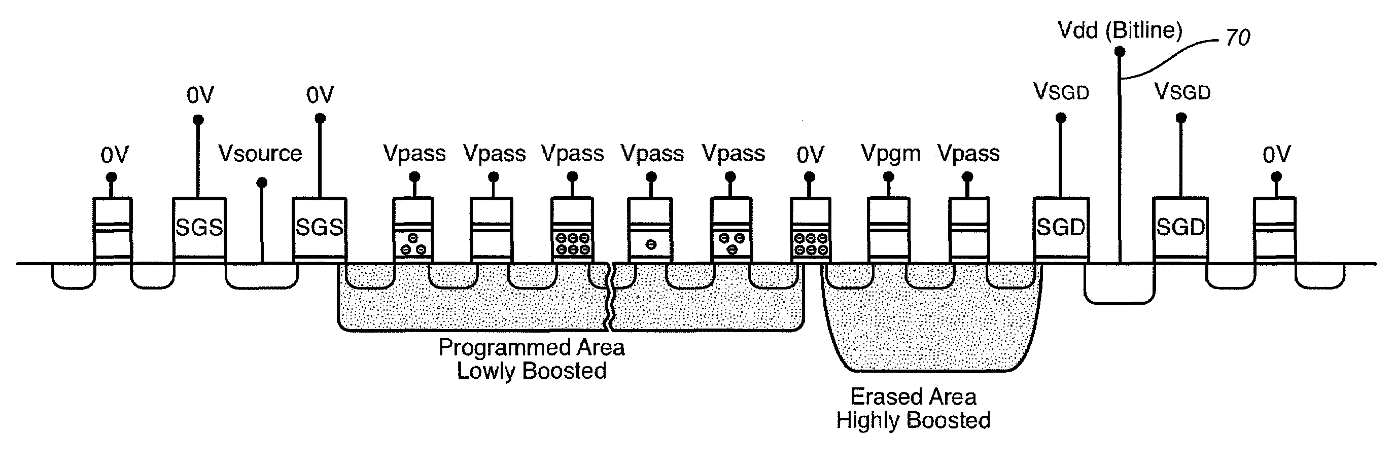
[0023]For example, one implementation of the above embodiment adopts a programming sequence where memory cells are programmed in a specified order with the cells closest to the source side select gate being programmed first, and sequentially programmed to the cells closest to the drain side select gate in the programming cycle. In this implementation, during one time interval of the programming cycle, the low isolation voltage is applied to the isolation word line that is at a larger distance from the selected word line compared with the case during an earlier time interval of the programming cycle. In other words, the number of word lines separating the isolation cell and the selected word line can be increased as the programming progresses towards the drain select gate. The result is that the channel region or area on the drain side of the isolation cell will not be too small, so that its capacitance also will not be so small as to result in the excessive vertical and / or lateral electric fields caused by the application of the program voltage Vpgm.
[0024]The above aspect of the invention can suppress the excessive boosting that results in a high electrical field at the isolation word line cell junction, especially when a word line close to the drain side select gate is selected for programming. Also, program disturb can be minimized because the isolation word line can be physically further away from the selected word line. The above aspect of the invention can be combined with any type of boosting method that currently exists. For example, another boosting method, such as the conventional EASB method or variations thereof can be used up to a certain word line selected for programming, while position of the isolation word line can be fixed (i.e. isolation voltage applied to the same fixed word line) when word lines closer to the drain side select gate are selected subsequently for programming. Alternatively, the number of word lines separating the isolation word line and the selected word line can be increased continually or intermittently or in any other manner as the programming progresses towards the drain side select gate. In these embodiments, all the other word lines in between the isolation word line and the selected word line can be set at any voltages. But, these embodiments would be most effective if voltages high enough are chosen to keep the drain side NAND string conductive, but not too high to avoid enhancing the high electric field in or around the isolation word line. Where boosting may be inadequate as the programming progresses towards the drain side select gate, relatively higher voltage(s) may be applied to word lines in between the isolation word line and the selected word line.
[0025]The above aspect of the invention is not limited to a scheme where memory cells are programmed in a specified order with the cells closest to the source side select gate being programmed first, and sequentially programmed to the cells closest to the drain side select gate in the programming cycle. Even where sequential source to drain programming is not used, substantially the same advantages can be attained when the programming is such that it avoids the above described situation that results in high lateral electric fields exists, such as where the isolation cell is too close to the drain side select gate in any EASB type of programming scheme. Such high vertical and lateral electric fields can be reduced by increasing the separation between the isolation word line and the selected word line when programming one or more word lines close to the drain side select gate.
[0026]According to another aspect of the invention, the programming is such that the isolation word line and the selected word line can be separated by at least two word lines. This reduces the high vertical and lateral electric fields that would otherwise exist in EASB type programming methods and systems. In one embodiment, all the word lines in between the isolation word line and the selected word line can be set at any voltages. But, this embodiment would be most effective if voltages high enough are chosen to keep the drain side NAND string conductive, but not too high to avoid enhancing the high electric field in or around the isolation word line. Where boosting may be inadequate as the programming progresses towards the drain side select gate, relatively higher voltage(s) may be applied to word lines in between the isolation word line and the selected word line. This aspect of the invention can be combined with any type of boosting method that currently exists. For example, another boosting method, such as the conventional EASB method or variations thereof can be used up to a certain word line in an initial part of the programming cycle. Then the programming can be such that the isolation word line and the selected word line to which the program voltage is applied is separated by at least two word lines in the remainder of the programming cycle. This aspect of the invention is not limited to a scheme where memory cells are programmed in a specified order with the cells closest to the source side select gate being programmed first, and sequentially programmed to the cells closest to the drain side select gate in the programming cycle. This aspect of the invention can be combined with another aspect described above by adjusting the number (e.g. by increasing the number to two or more) of word lines between the isolation word line and the selected word line as a function of distance of the selected word line from the drain side select gate.

Problems solved by technology

As noted above, in conventional programming schemes such as EASB, high electric field enhanced program disturb characteristic is worse when programming the cells closer to the drain side select gate.

Method used


Image

  • Self-boosting method with suppression of high lateral electric fields
  • Self-boosting method with suppression of high lateral electric fields
  • Self-boosting method with suppression of high lateral electric fields

Examples


Embodiment Construction

Memory System

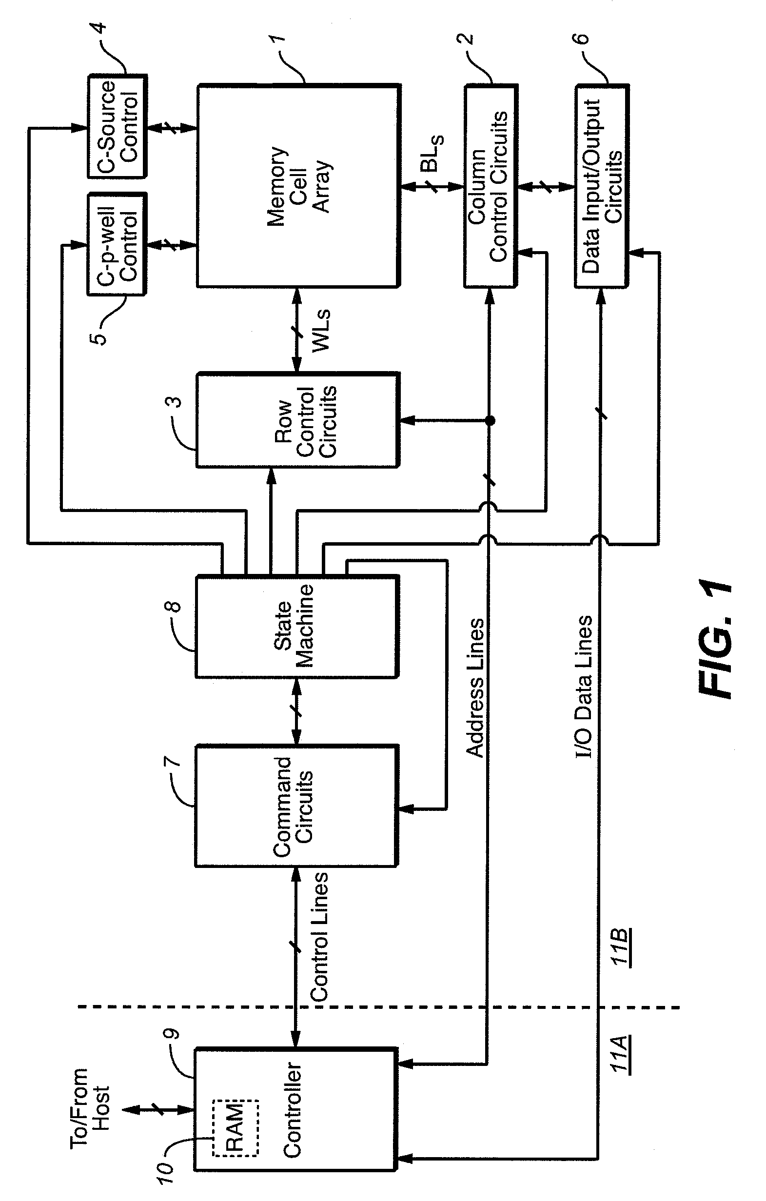
[0040]An example memory system in which the various aspects of the present invention may be implemented is illustrated by the block diagram of FIG. 1. A memory cell array 1 including a plurality of memory cells M arranged in a matrix is controlled by a column control circuit 2, a row control circuit 3, a c-source control circuit 4 and a c-p-well control circuit 5. The memory cell array 1 is, in this example, of the NAND type that is described above in the Background and in references incorporated herein by reference. A control circuit 2 is connected to bit lines (BL) of the memory cell array 1 for reading data stored in the memory cells (M), for determining a state of the memory cells (M) during a program operation, and for controlling potential levels of the bit lines (BL) to promote the programming or to inhibit the programming. The row control Circuit 3 is connected to word lines (WL) to select one of the word lines (WL), to apply read voltages, to apply program volt...


PUM


Abstract

In an improved EASB programming scheme for a flash device (e.g. a NAND flash device), the number of word lines separating a selected word line (to which a program voltage is applied) and an isolation word line (to which an isolation voltage is applied) is adjusted as a function (e.g. inverse function) of distance of the selected word line from the drain side select gate to reduce program disturb due to high vertical and lateral electric fields at or near the isolation transistor when programming word lines closer to the drain side select gate. The selected and isolation word lines are preferably separated by two or more word lines to which intermediate voltage(s) are applied.

Description

CROSS-REFERENCE TO RELATED APPLICATION[0001]This application is related to U.S. patent application Ser. No. 11 / 394,803, entitled, “Self-Boosting System with Suppression of High Lateral Electric Fields”, filed on the same day as the present application; which application is incorporated in its entirety by reference as if fully set forth herein.BACKGROUND OF THE INVENTION[0002]This invention relates generally to non-volatile semiconductor memories of the flash EEPROM (Electrically Erasable and Programmable Read Only Memory) type, particularly to structures and methods of operating NAND types of memory cell arrays.[0003]There are many commercially used today, successful non-volatile memory products being used today, particularly in the form of small form factor cards, which use an array of flash EEPROM cells.[0004]One popular flash EEPROM architecture utilizes a NAND array, wherein a large number of strings of memory cells are connected through one or more select transistors between in...

Claims


Application Information

Patent Timeline
Patent Type & Authority Patents(United States)
IPC IPC(8): G11C16/04
CPCG11C16/0483H01L27/115G11C16/3427G11C16/12H10B69/00
Inventor OOWADA, KEN
Owner SANDISK TECH LLC
Learn More