
System and method for monitoring train arrival and departure latencies

a technology for arrival and departure latencies and systems, applied in the field of railyards, can solve problems such as inaccurate picture of railyard operations, high cost and complexity and complex installation of aei tag reading systems

Active Publication Date: 2008-09-23
GENERAL ELECTRIC CO
View PDF13 Cites 15 Cited by
  • Summary
  • Abstract
  • Description
  • Claims
  • Application Information

AI Technical Summary

Benefits of technology

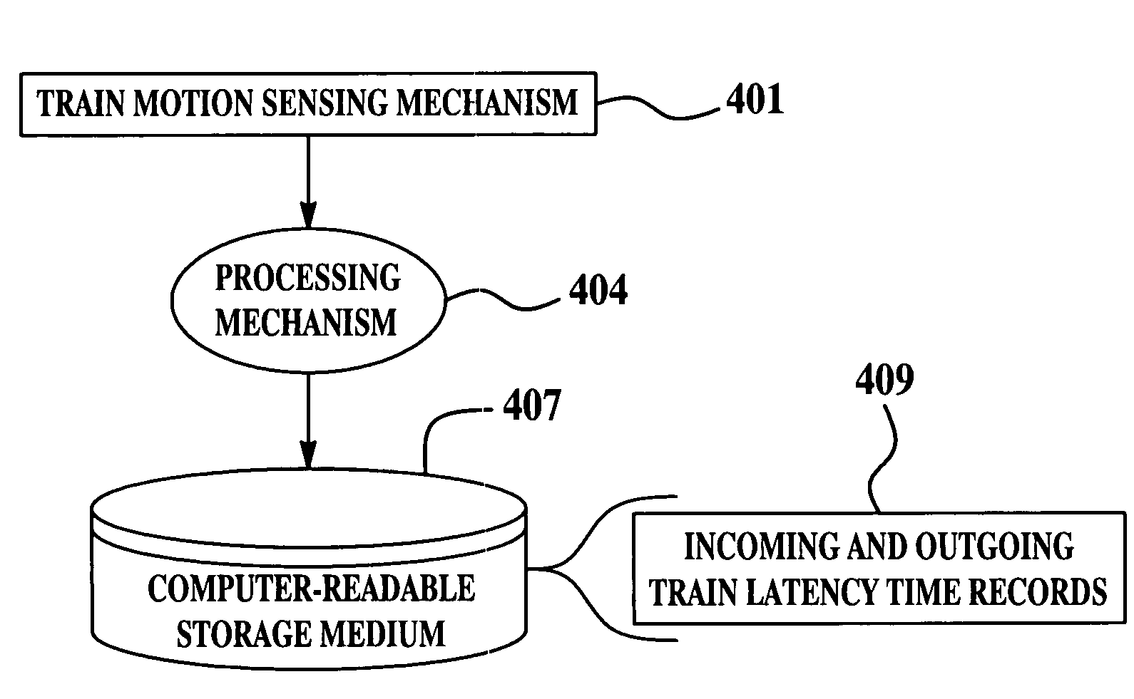
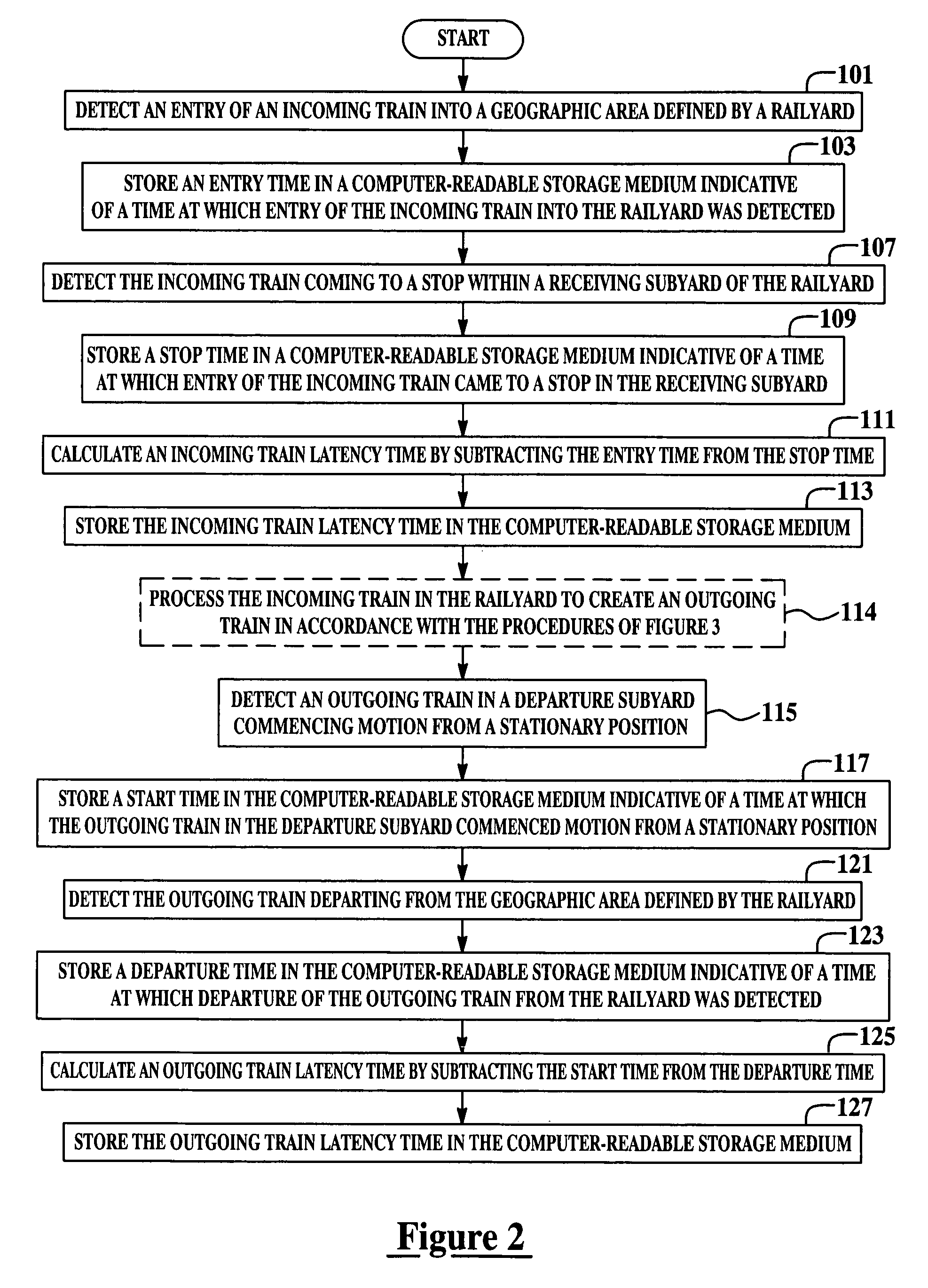
"The patent describes a system for monitoring trains in a railyard. The system detects the arrival and stop of incoming trains, and calculates the time it takes for the train to pass through the railyard. This information is stored in a computer-readable medium. The system can also detect the acceleration and departure of outgoing trains, and calculate the time it takes for the train to leave the railyard. This information is also stored in the computer-readable medium. The technical effect of this system is to improve safety and efficiency in managing train movements in the railyard."

Problems solved by technology

The various services in a railyard compete for resources such as personnel, equipment, and space in various facilities so that managing the entire railyard efficiently is a complex operation.
AEI tag reading systems are expensive and complicated to install.
Due to the amount of RF energy that must be transmitted by the AEI tag reader so as to obtain tag readings, some of this energy travels beyond the limits of the railyard where it may interfere with communications equipment.
The times at which trains enter and exit the railyard may create a potentially inaccurate picture of railyard operations unless additional information is acquired.
However, due to congestion, crew availability, yard conditions, or other factors, it may not be possible to bring the train immediately into a receiving subyard so as to complete a train arrival process.
Each individual railcar is delayed, thus impacting the performance metrics of the entire railyard and possibly causing delays in subsequent outbound trains from that yard.
Both of these approaches require significant capital expenditure, installation labor, and electrical cable trenching which disrupts operations within the railyard.
The foregoing considerations render existing track occupancy monitoring approaches undesirable and prohibitive.

Method used


Image

  • System and method for monitoring train arrival and departure latencies
  • System and method for monitoring train arrival and departure latencies
  • System and method for monitoring train arrival and departure latencies

Examples


Embodiment Construction

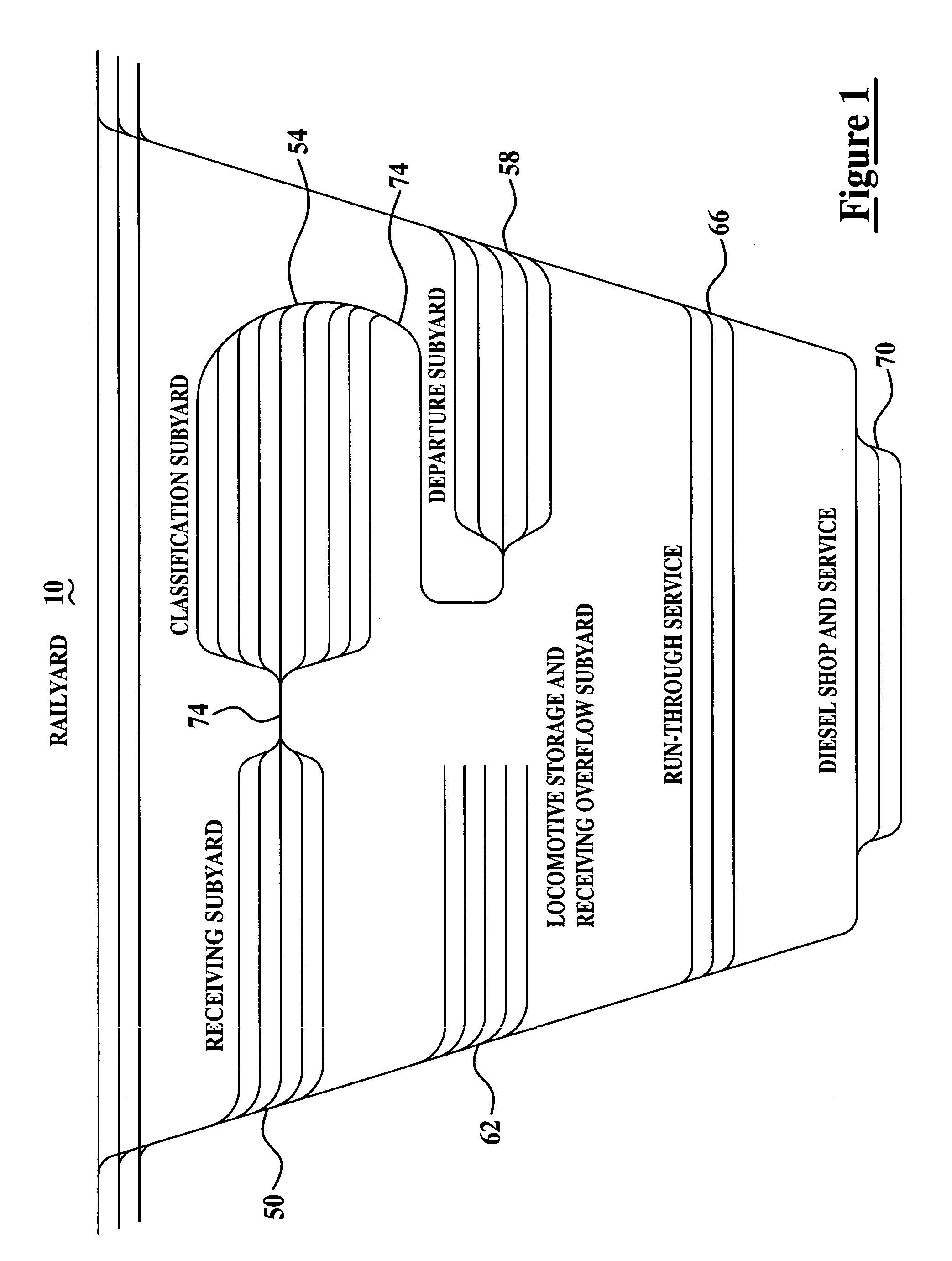
[0017]FIG. 1 is a diagram of a railyard 10 for illustrating the various areas of the railyard that trains pass through during railyard processing. Railyard 10 includes various sets of tracks dedicated to specific uses and functions. For example, an incoming train arrives in a receiving subyard 50 and is assigned a specific receiving track. At some later time, a switch engine enters the receiving track and moves the railcars into a classification subyard 54. Classification subyard 54 is sometimes referred to as a “bowl”. The tracks in classification subyard 54 are assigned to hold specific blocks of railcars being assembled for outbound trains. When assembly of a block of railcars is completed, this block of railcars is assigned to a specific track in a departure subyard 58 reserved for assembling a specific outgoing train.

[0018]When all blocks of railcars required for an outgoing train are assembled, one or more locomotives from a locomotive storage and receiving overflow subyard 62...


PUM


Abstract

Methods and systems for monitoring trains in a railyard. These methods and systems detect an incoming train entering a geographic area defined by a railyard, store an entry time indicative of a time at which the incoming train entering the railyard was detected, detect the incoming train coming to a stop in a subyard of the railyard, store a stop time indicative of a time at which the incoming train came to a stop in the receiving subyard, calculate an incoming train latency time by subtracting the entry time from the stop time, and store the incoming train latency time as an incoming train latency time record.

Description

BACKGROUND[0001]This invention relates generally to railyards and, more particularly, to monitoring train arrival and departure latencies for a railyard.[0002]Railyards are the hubs of railroad transportation systems. Therefore, railyards perform many services, for example, freight origination, interchange and termination, locomotive storage and maintenance, assembly and inspection of new trains, servicing of trains running through the facility, inspection and maintenance of railcars, and railcar storage. The various services in a railyard compete for resources such as personnel, equipment, and space in various facilities so that managing the entire railyard efficiently is a complex operation.[0003]In order to improve the efficiency of railyard operations, it would be useful for an automatic system to monitor the times at which trains enter a geographic area defining a railyard and, subsequently, leave the railyard. Determination of train entry and exit from the railyard is currentl...

Claims


Application Information

Patent Timeline
Patent Type & Authority Patents(United States)
IPC IPC(8): B61L17/00G06F17/00
CPCB61L17/00
Inventor DAVENPORT, DAVID MICHAELBHOTIKA, RAHULHERSHEY, JOHN ERIKMITCHELL, ROBERT JAMESANDARAWIS, EMAD ANDARAWISWELLES, KENNETH BRAKELEY
Owner GENERAL ELECTRIC CO
Learn More