Electrically controlled in-muffler exhaust valve for use during cylinder deactivation

a technology of in-muffler exhaust valve and cylinder deactivation, which is applied in the direction of functional valve types, machines/engines, mechanical apparatus, etc., can solve the problems of large weight of cast housing, reliability problems, and vacuum actuator reliability problems

Active Publication Date: 2008-09-30
ET US HLDG
View PDF13 Cites 15 Cited by
  • Summary
  • Abstract
  • Description
  • Claims
  • Application Information

AI Technical Summary

Benefits of technology

[0006]The invention provides a powertrain control system including an engine having multiple cylinders. A controller selectively activates the cylinders to provide a cylinder combination having a desired power displacement. In one example powertrain control system, the controller selectively activates the cylinders between a V-8 and V-4 mode. An exhaust system having a valve and an electrical actuator selectively electrically actuates the valve in response to the controller between multiple positions. In an example of the invention, the electrical actuator moves the valve from an open position in V-8 mode to a partially closed position in V-4 mode to increase back pressure and reduce NVH issues in V-4 mode.
[0008]Accordingly, the present invention provides an improved powertrain system providing variable tuning in displacement on demand engine configurations.

Problems solved by technology

One challenge of commercializing displacement on demand engine configurations is that the change between engine modes must be transparent to the vehicle operator.
However, when the cylinders are deactivated to change from V-8 to V-4 mode the exhaust system produces a tinny or hollow sound considered undesirable to the vehicle operator.
The cast housing has considerable weight and presents reliability issues and increased assembly attributable to the connections between the cast housing and the adjacent exhaust system components.
Furthermore, the vacuum actuator presents reliability issues resulting from the considerable length the vacuum hoses and connections, which may be damaged during off road vehicle use or assembly at the vehicle assembly plant.
Moreover, since the actuator is vacuum operated, limited control over the valve is possible since its operation is based upon engine manifold pressure.
Furthermore, the vacuum actuator lacks safeguards in the event of an actuator or valve malfunction.

Method used


Image

  • Electrically controlled in-muffler exhaust valve for use during cylinder deactivation
  • Electrically controlled in-muffler exhaust valve for use during cylinder deactivation
  • Electrically controlled in-muffler exhaust valve for use during cylinder deactivation

Examples


Embodiment Construction

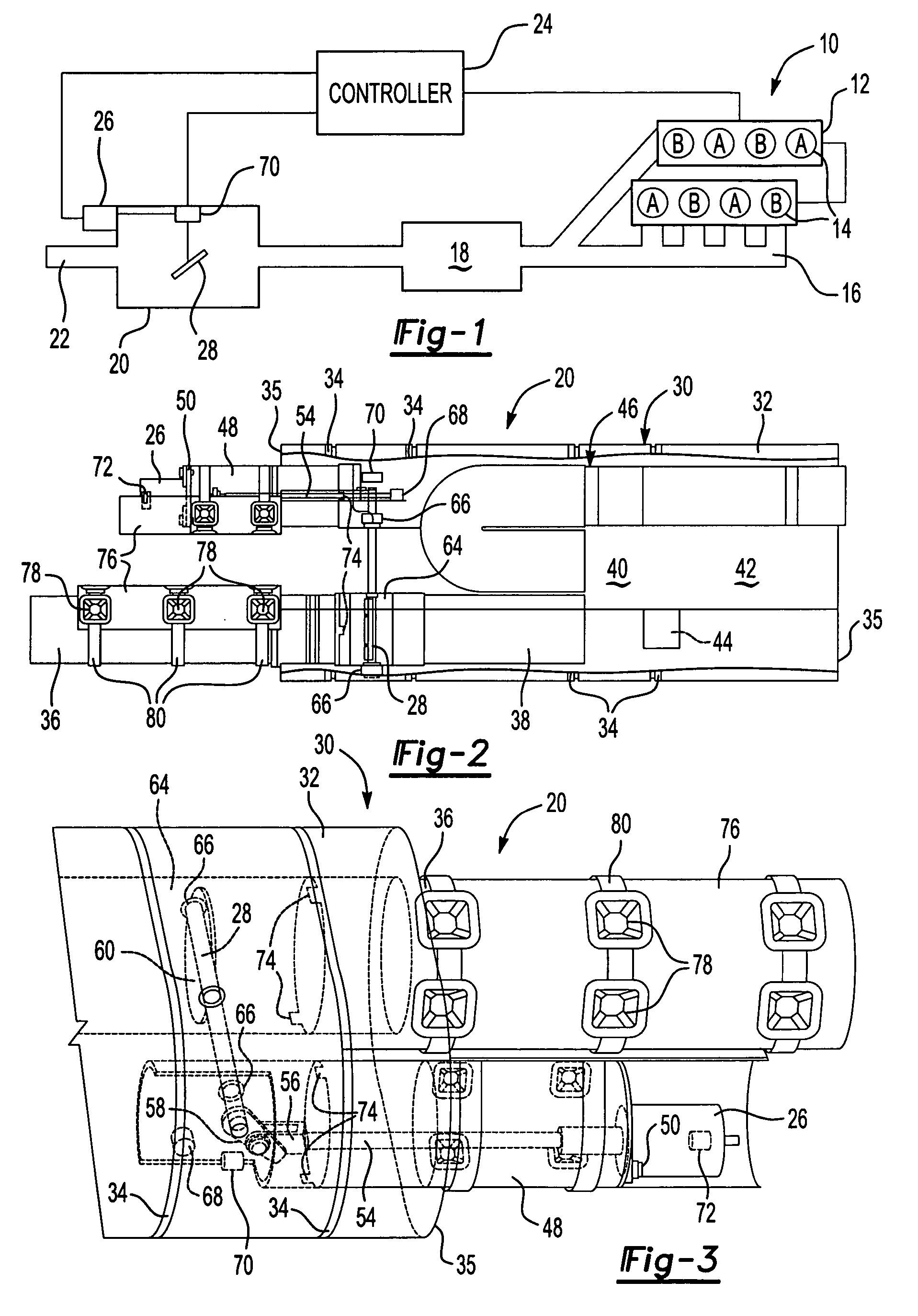
[0014]A powertrain control system 10 is shown in FIG. 1. The system 10 includes an internal combustion engine 12 having multiple cylinders 14. In the example shown, there are eight cylinders having two groups, A and B. In a V-8 mode both cylinders A and B are activated, for example by supply fuel to all cylinders, so that all eight cylinders provide power to the vehicle. In a V-4 mode only cylinders A are activated so that only four cylinders provide power to the vehicle, for example by cutting fuel to cylinders B, thereby reducing fuel consumption and increasing fuel economy during vehicle operating conditions in which reduced engine power is not noticeable to the vehicle operator. It should be understood, however, that although the invention has been discussed with reference to V-8 and V-4 modes, other engine configurations having other displacement configurations and modes may also be used with this invention.

[0015]The system 10 includes an exhaust system 17 receiving exhaust gas...


PUM


Abstract

A powertrain control system is provided that includes an engine having multiple cylinders. A controller selectively activates the cylinders to provide a cylinder combination having a desired power displacement. In one example powertrain control system, the controller selectively activates the cylinders between a V-8 and V-4 mode. An exhaust system having a valve and an electrical actuator selectively electrically actuates the valve in response to the controller between multiple positions. The electrical actuator moves the valve from an open position in V-8 mode to a partially closed position in V-4 mode to increase back pressure and reduce NVH issues in V-4 mode. A muffler includes a housing having an exhaust passage. The valve is supported by the housing and arranged in the exhaust passage. The valve is moveable between multiple positions for tuning the muffler. The electrical actuator is supported by the housing to actuate the valve between the multiple positions.

Description

BACKGROUND OF THE INVENTION[0001]This invention relates to an exhaust system having a valve for reducing noise, vibration and harshness (NVH). In particular, the invention relates to an electrically controlled in-muffler exhaust valve for displacement on demand internal combustion engines.[0002]Automobile manufacturers are continuing to develop vehicles having greater fuel economy. In particular, larger vehicles having larger displacement engines have been targeted for better fuel economy. One solution to provide a more fuel efficient vehicle is so-called displacement on demand engines that have cylinder selectively activated depending upon operating conditions. For example, a V-8 operates in V-8 mode when the vehicle requires more power such as towing a trailer. The powertrain control system deactivates four of the cylinders so that the engine operates in V-4 mode when the vehicle requires less power such as when it is lightly loaded and cruising at highway speeds.[0003]One challen...

Claims


Application Information

Patent Timeline
Patent Type & Authority Patents(United States)
IPC IPC(8): F01N1/08F01N1/16F01N11/00F01N13/14F01N13/18F02D9/04F02D17/02
CPCF01N1/163F01N1/166F01N13/14F02D17/02F01N13/1844F02D9/04F01N13/1805
Inventor NOHL, JOHN P.WOEMER, DAVID R.CALLAHAN, JOSEPH E.
Owner ET US HLDG
Why Eureka
Try Eureka