Painting system

a technology of painting system and painting surface, which is applied in the direction of manipulators, coatings, program-controlled manipulators, etc., can solve the problems of limited transverse movement range, inability to track the object to be painted, and high cost of track means comprising rails, so as to reduce the waste of paint, improve the production capacity of the robot installed, and reduce the effect of paint was

Active Publication Date: 2008-09-30
ABB (SCHWEIZ) AG
View PDF39 Cites 24 Cited by
  • Summary
  • Abstract
  • Description
  • Claims
  • Application Information

AI Technical Summary

Benefits of technology

[0009]A primary object of the present invention is to provide a paint system for large objects, which involves a lesser number of stationary painting robots, involving a smaller paint booth and which offers a higher production capacity per robot installed. A paint booth in this context is a sealed of environment comprising a floor, a ceiling and walls which have openings for receiving a car body traveling on a conveyor. The painting robot directed to in this invention is a stationary mounted industrial robot with a painting tool such as a spray painting means (painting gun) attached to its end effector. A secondary object of the invention is to provide a painting system that offers higher operation efficiency and less paint waste.
[0013]Normally each of the two painting robots in the booth are arranged for painting half of an object. This implies that the two arms of each robot must together reach all positions of each halves of the object. Thus the minimum length of the first and the second arm together must be longer than half the length of the object. Since the first and second arm must be able to fold upon each other they are in a preferred embodiment equal in length. Thus with this configuration the length of each arm must be equal or longer than a fourth of the length of the object to be painted. In a further development of this embodiment the second arm comprises a bended structure for better reach performance.
[0014]Since the two painting robots are arranged to cover each halves of the object there is no need for a third painting robot. However in situations where the production capacity must be increased or if the object to be painted is very big a third painting robot must be installed. Such a third robot may be fixed in a wall position higher than the first and second painting robot. In a further embodiment of the invention the robot arrangement comprises a control means that makes able the painting robots following an object to be painted continuously moving through the booth.
[0015]According to a second aspect of the invention the objects are achieved by a method of painting an object in long continuous strokes. A paint stroke begins with the spray painting gun being oriented in position prior to a path to be painted. The movement begins and at a position just before the start point of the path the gun is turned on. The robot then moves the spray gun along the path at predetermined distance and at a direction normal to the surface of the path. When reaching the end of the path the gun is kept in operation until it has fully passed the path end before the gun is turned off. Then the movement stops and the stroke is completed. Along such a stroke the spray operation of the gun may arbitrarily be turned on or off accounting for openings in a car body such as for instance an opening for receiving a window. In a preferred embodiment the length of such a stroke is equal or longer than the object to be painted. By this longer painting strokes the number of time consuming re-orientation of the gun is reduced. This will result in a more efficient time management of the spraying operation. By using longer strokes the object will be fully painted with fewer strokes. Since there is a moment in the beginning and at the end of each stroke where paint is wasted the total paint waste of a painting operation is reduced.

Problems solved by technology

Apparatus of this type may have a sufficient range of reciprocal motion in the vertical direction, but have rather limited ranges of motion in the transverse direction of the painting booth, and practically no option for tracking the object to be painted in the direction of the conveyor motion through the booth.
Track means comprising rails however are costly and very delicate in function on dirt and particles on the rails.
Thus it is difficult to keep track of the robot position on the rails.
The more manipulators inside the painting booth necessary for painting the object the higher the investment costs.
A larger number of manipulators to be controlled to simultaneously paint the object normally results in a very complex software programming.
Thus there is a collision of demands.
This arrangement of course affects the performance of the robot.
The robot then is only capable of making short paint strokes.
An increased number of short paint strokes calls for an increased number of time consuming re-orientation operations and severe waste of paint.

Method used


Image

  • Painting system
  • Painting system
  • Painting system

Examples


Embodiment Construction

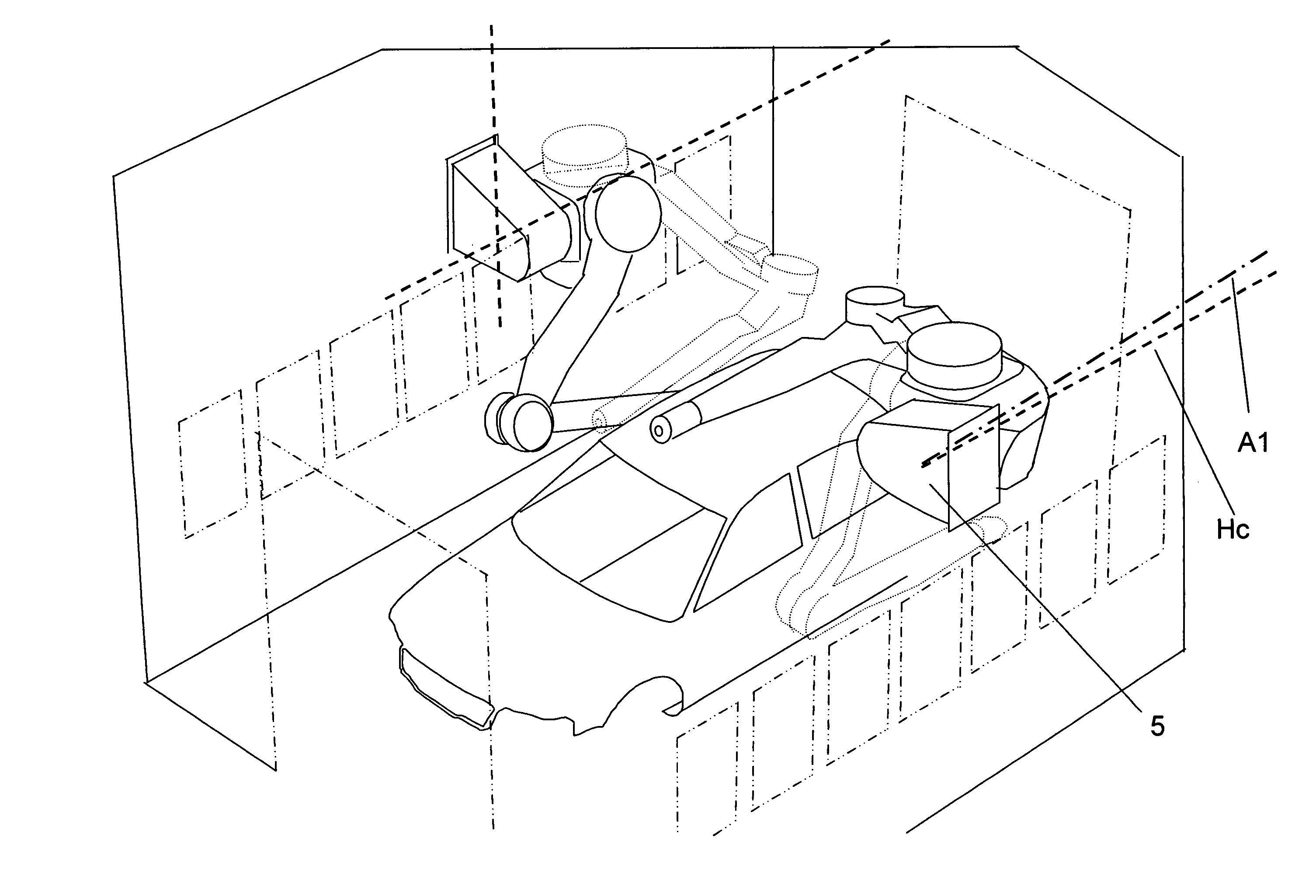
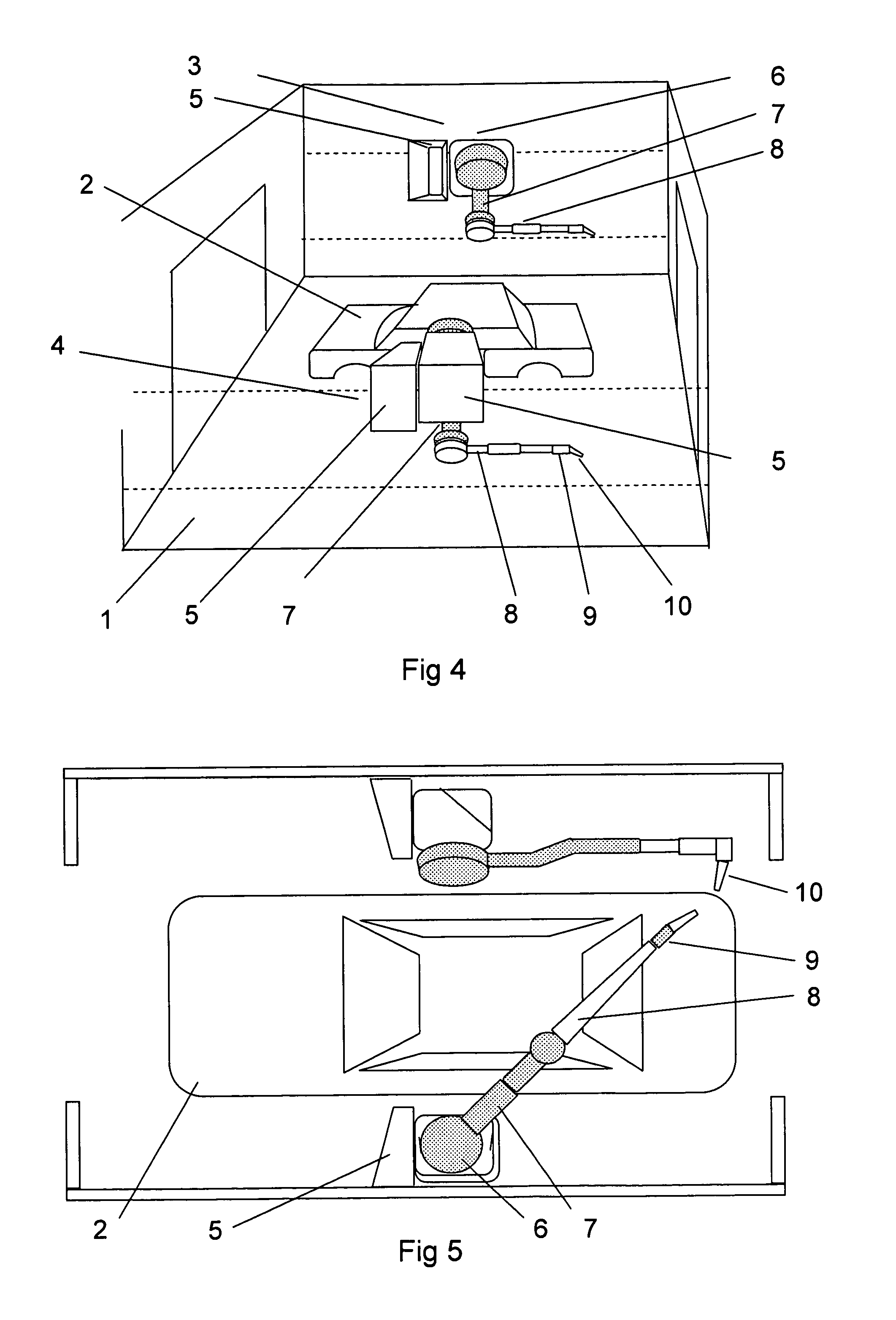
[0026]According to FIG. 4 a painting system according to the invention comprises a painting booth 1, in which is placed an object, a car body, 2 to be painted. The booth also comprises a first painting robot 3 and a second painting robot 3. Each of the painting robots comprises a base 5 attached to the wall of the booth. The base comprises a cantilever construction and carries a stand 6 rotatably arranged around a first axis, which in the embodiment shown is oriented in the direction of the length of the booth. The stand carries a first arm 7 rotatably arranged around a second axis, which in the embodiment shown is oriented normal to the first axis. The first arm carries a second arm 8 rotatably arranged around a third axis, which in the embodiment shown is oriented parallel to the second axis. The second arm carries an end effector comprising an arm part arrangement 9 with three degrees of freedom moveability. Finally the end effector arrangement caries a painting tool 10 in the fo...


PUM


Abstract

Painting system for painting large objects comprising a paint booth with surrounding walls and a robot installation comprising a plurality of painting robots, each painting robot comprising a stationary base, a stand carried by the base rotatably arranged around a first axis, a first arm carried by the stand rotatably arranged around a second axis, a second arm carried by the first arm rotatably arranged around a third axis and a forth, a fifth and a sixth arm part carried by the second arm for orienting an attached painting tool.

Description

CROSS-REFERENCE TO RELATED APPLICATIONS[0001]This application claims priority to U.S. provisional patent application 60 / 487,940 filed Jul. 18, 2003.TECHNICAL FIELD[0002]This present invention concerns a painting system comprising a paint booth and a robot installation for painting large objects inside the painting booth. More precisely the invention concerns such a painting system including a paint booth with walls isolating the object to be painted from the surroundings. Especially the invention concerns such a system wherein the robot installation contains at least two industrial robots, each comprising at least four axes for servo-controlled movements. An industrial robot in this context comprises a manipulator with electric motors and a control means containing power means for driving the motors and computer means which by instructions from a computer program is arranged for sensing and controlling the manipulator movementsBACKGROUND OF THE INVENTION[0003]Painting of car bodies ...

Claims


Application Information

Patent Timeline
Patent Type & Authority Patents(United States)
IPC IPC(8): B05B3/00B05B15/12B05B7/06B05B1/28B25J9/06B05B12/00B05B13/04B05C5/00B05D1/02B25J9/00
CPCB05B13/0452B25J19/0079B25J9/0084B25J11/0075B05B13/0431B05B15/12B05B16/00
Inventor KROGEDAL, ARNULFBRYNE, GISLE
Owner ABB (SCHWEIZ) AG
Why Eureka
Try Eureka