Successive vapour deposition system, vapour deposition system, and vapour deposition process

a vapour deposition system and vapour deposition technology, applied in vacuum evaporation coatings, electroluminescent light sources, coatings, etc., can solve the problems of inability to avoid excessive consumption time-consuming and inefficient operation, etc., to achieve the effect of reducing the waste of vapor deposition materials and time-consuming

Inactive Publication Date: 2008-09-30
ROHM CO LTD +1
View PDF15 Cites 24 Cited by
  • Summary
  • Abstract
  • Description
  • Claims
  • Application Information

AI Technical Summary

Benefits of technology

[0007]The present invention is devised in view of the problems noted above, and accordingly provides a vapor deposition system which makes it possible to

Problems solved by technology

In such conventional successive vapor deposition systems, the substrate needs to be successively displaced from one chamber to another, among the plurality of vacuum deposition chambers, via the central vacuum carrier robotic chamber, which is a time-consuming and inefficient operation.
In addition, vapor deposition materials are consumed excessively because of the fundamental structure of the conventional systems in which vacuum deposition chambers are merely arranged around the central vacuum carrier robotic chamber.
However, an excessive consumption of the vapor deposition materials cannot be avoided because the evenness of the layers is ensured only by depositing a portion of vaporized molecules onto the substrate, the vaporized molecules of which are spread out widely upwards in all directions from crucibles or bo

Method used


Image

  • Successive vapour deposition system, vapour deposition system, and vapour deposition process
  • Successive vapour deposition system, vapour deposition system, and vapour deposition process
  • Successive vapour deposition system, vapour deposition system, and vapour deposition process

Examples


Embodiment Construction

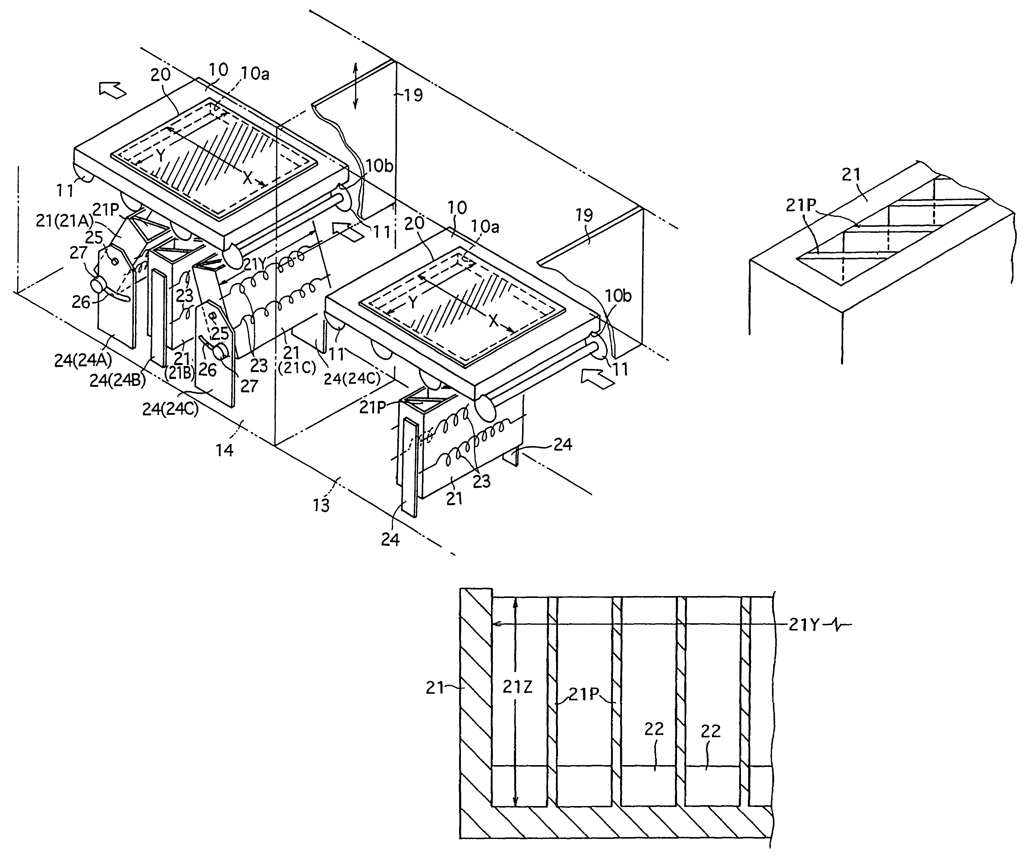
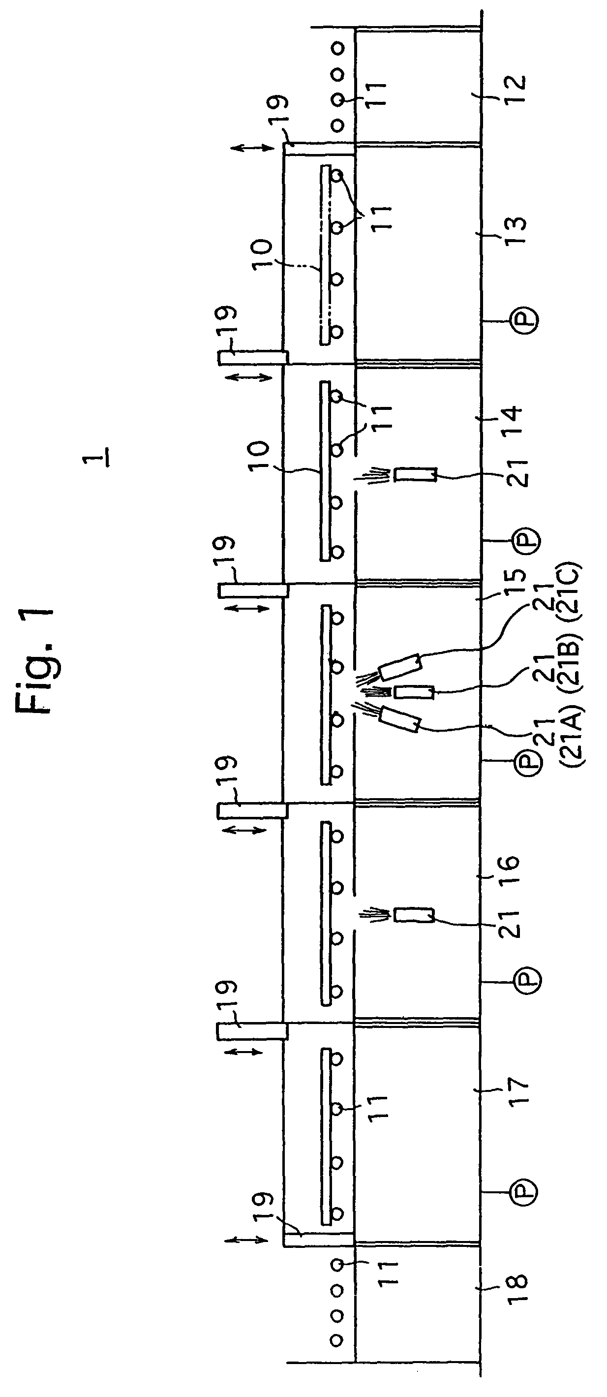
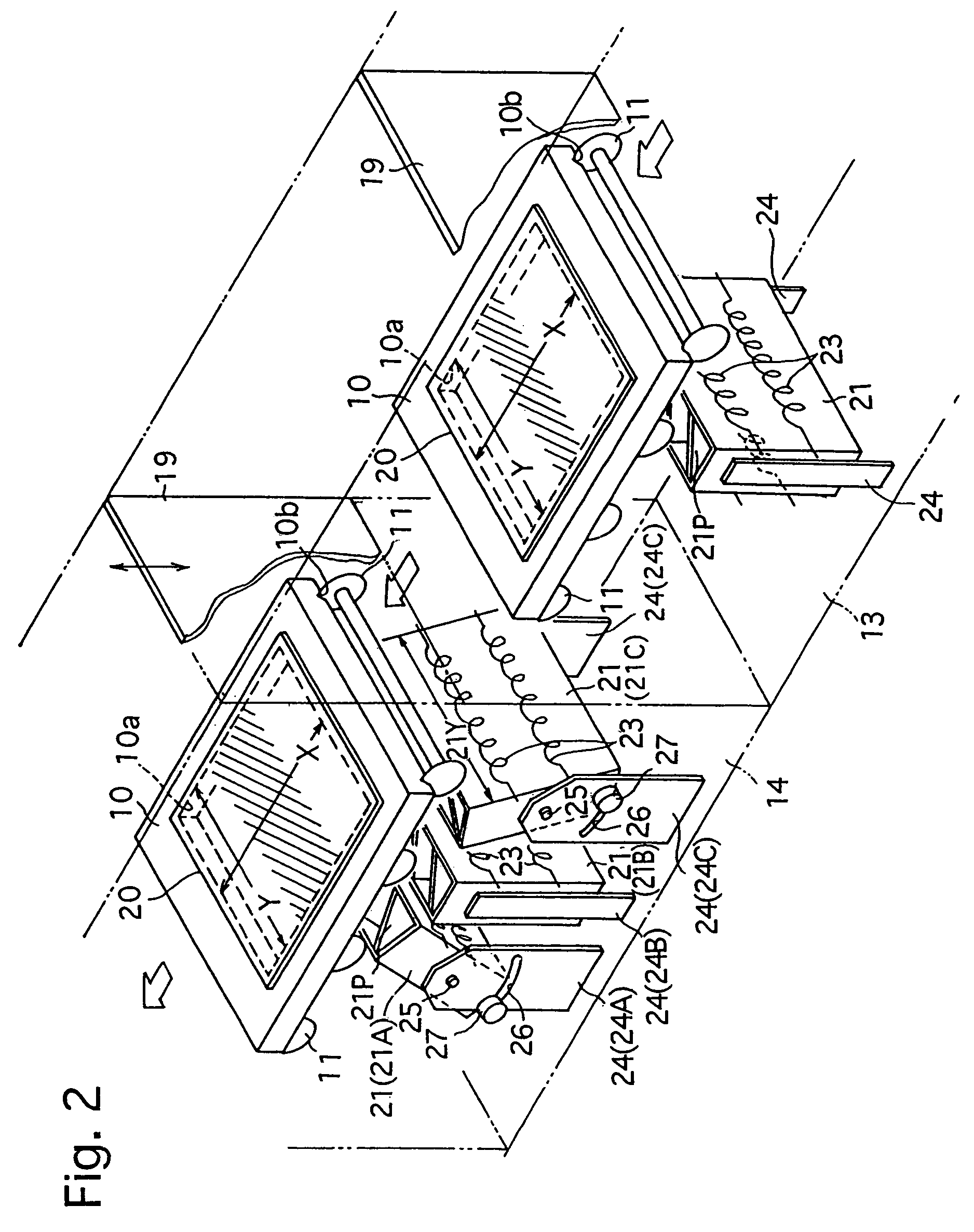
[0037]FIG. 1 shows an embodiment of a successive vapor deposition system according to the present invention. The successive vapor deposition system 1 is provided with a plurality of substrate holders 10 and a plurality of conveying rollers 11 which conveys the substrate holders 10 from right to left as viewed in FIG. 1. The plurality of substrate holders 10 and the plurality of conveying rollers 11 constitute a conveyer. The plurality of conveying rollers 11 are driven by a motor (not shown). The successive vapor deposition system 1 is provided, in a conveying direction of the substrate holders 10 (the horizontal-leftward direction as viewed in FIG. 1; hereinafter referred to as “conveying direction”), with a preparation stage 12, a preliminary vacuum chamber 13, a first vapor deposition chamber 14, a second vapor deposition chamber (co-deposition chamber) 15, a third vapor deposition chamber 16, a preliminary ejection chamber 17 and an ejection stage 18, in this order from right to...


PUM

PropertyMeasurementUnit
Angleaaaaaaaaaa
Areaaaaaaaaaaa
Depthaaaaaaaaaa

Abstract

A successive vapor deposition system in which a vapor deposition material is heated, vaporized in a vacuum, and deposited onto a vapor deposition area of a substrate, includes a conveyer which conveys the substrate in a conveying direction parallel to a plane on which the substrate lies, wherein the vapor deposition area faces downward and is exposed through the underside of the conveyer; a plurality of vapor deposition chambers aligned in the conveying direction, each the vapor deposition chamber including a space through which the substrate is conveyed; at least one container positioned in each of the plurality of vapor deposition chambers below the plane on which the substrate lies, and containing the vapor deposition material, wherein a width of the container covers the vapor deposition area in a direction perpendicular to the conveying direction; and a heating medium provided for the container.

Description

BACKGROUND OF THE INVENTION[0001]1. Field of the Invention[0002]The present invention relates to a successive vapor deposition system suitable for successive formation of thin layers of different vapor deposition materials onto a substrate. The present invention also relates to a vapor deposition system and a vapor deposition process.[0003]2. Description of the Related Art[0004]A typical organic electroluminescent device generally has a hole-transporting layer, a luminescent layer, an electron-transporting layer and an electrode layer which are formed by vacuum deposition successively on an ITO (Indium tin oxide) glass substrate. In conventional successive vapor deposition systems for forming such successive layers on the glass substrate, a plurality of vacuum deposition chambers (which include a substrate stock chamber and a preliminary treatment chamber) for evaporating different vapor deposition materials onto the glass substrate are arranged radially with respect to a central va...

Claims


Application Information

Patent Timeline
IPC IPC(8): C23C16/00H05B33/10C23C14/12C23C14/24C23C14/56H01L21/205H01L51/00H01L51/30H01L51/40H01L51/50
CPCC23C14/12C23C14/24C23C14/243C23C14/568H01L51/001H01L51/5012H01L51/005H01L51/0052H01L51/0059H10K71/164H10K85/60H10K85/631H10K85/615H10K50/11H01L21/205
Inventor KIDO, JUNJIMIZUKAMI, TOKIO
Owner ROHM CO LTD
Why Eureka
Try Eureka