Radio repeater and radio relay transmission method

a radio repeater and radio relay technology, applied in the field of radio relaying, can solve the problems of difficult to move the location of the radio repeater, inconvenient to relay in a communication system, and the amount of signals which can be transmitted is nearly halved in comparison to a continuous relaying operation, so as to reduce the coupling, increase the number of transmission paths, and increase the channel capacity

Inactive Publication Date: 2008-09-30
NTT DOCOMO INC
View PDF10 Cites 69 Cited by
  • Summary
  • Abstract
  • Description
  • Claims
  • Application Information

AI Technical Summary

Benefits of technology

[0011]With the radio repeater according to the present invention, a received radio signal is transmitted from a transmission antenna having a polarization which is orthogonal to the polarization of the reception antenna to decouple between the transmission and the reception antenna. In addition, at least one of loop interference signals from the first and second transmission antennas having polarizations which are orthogonalized relative to each other is suppressed from the antenna received radio signal, thus reducing a coupling between the transmission and the reception antenna.
[0012]With the radio relay transmission method according to the present invention, the use of a radio repeater increases the number of transmission paths from a transmitter to a receiver, and the radio repeater is allowed to perform the reception and transmission simultaneously for the reception antenna and the transmission antenna having polarizations which are orthogonalized, permitting a continuous relaying and amplifying operation to be achieved, thus increasing the channel capacity. There is no need to provide a narrow directivity beam for the reception antenna of the radio repeater, and the radio repeater can be moved.

Problems solved by technology

In addition, in a conventional radio repeater, the directional beam of the reception antenna thereof is directed in the direction of the transmitter antenna, and this presents a difficulty in moving the location of the radio repeater.
The separation between different polarizations as disclosed in the cited Japanese Laid-Open Patent Application relates to a communication between opposing stations, and is not suited to a relaying in a communication system such as a mobile communication.
In a conventional radio relay transmission method of MIMO type, for example, in the method illustrated in FIG. 2, even though the number of transmission paths can be increased, the radio repeater once stores received radio signals, and then transmits the stored radio signals while the transmission from the transmitter is interrupted in order to avoid the loop interference problem which occurs at the radio repeater, or the reception and the transmission take place at the radio repeater in a time division manner, resulting in a disadvantages that the amount of signals which can be transmitted is nearly halved in comparison to a continuous relaying operation.

Method used


Image

  • Radio repeater and radio relay transmission method
  • Radio repeater and radio relay transmission method
  • Radio repeater and radio relay transmission method

Examples


embodiment 1

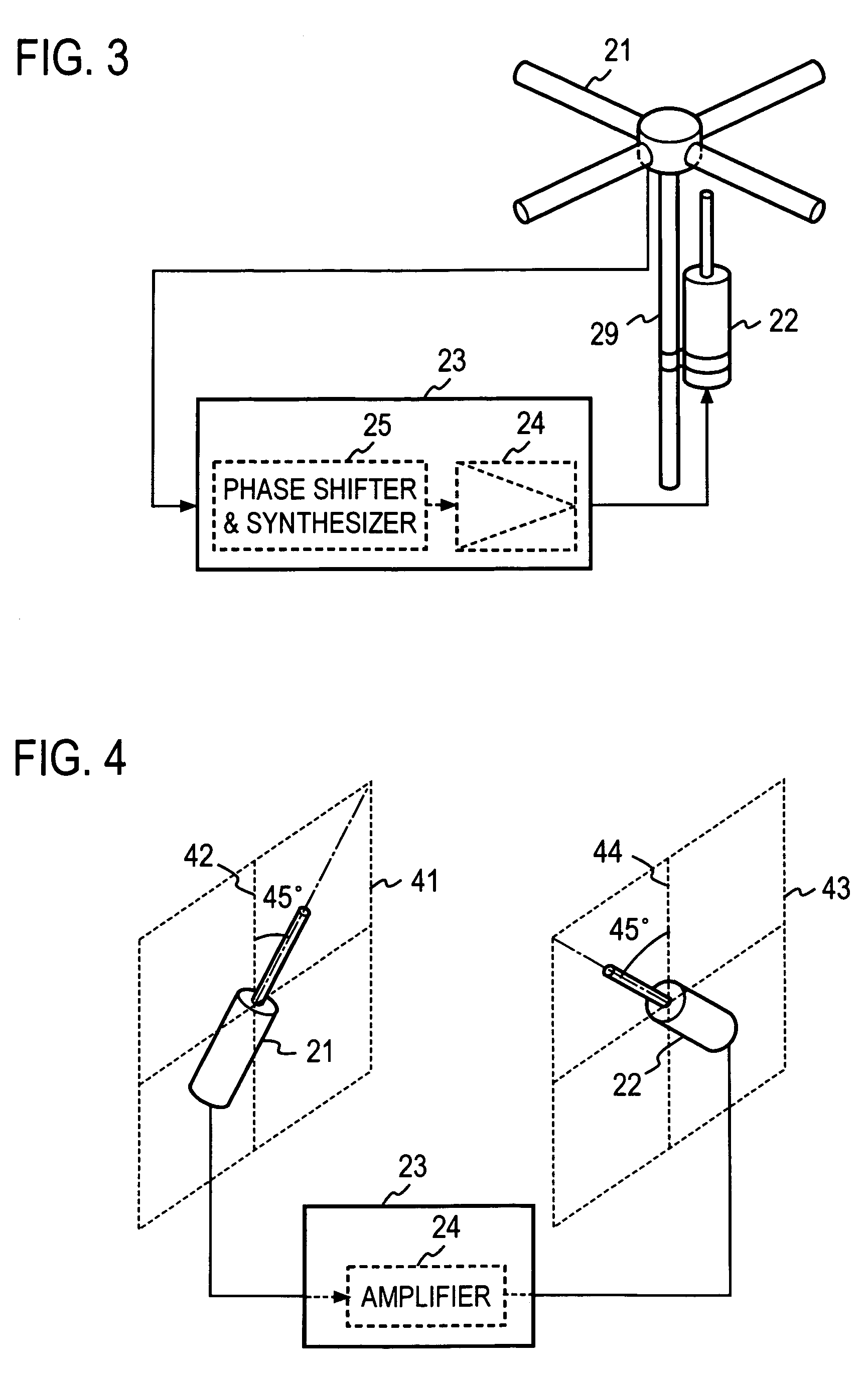
[0045]The likelihood of an oscillation occurring in the repeater shown in FIG. 6 arises from the following reason: for example, a radio signal received by the first-polarization reception antenna 211 is transmitted from the second-polarization transmission antenna 221 and this radio signal is received by the second-polarization reception antenna 212 through a loop interference transmission path 41. The received loop interference signal is amplified by the amplifier 242 to be transmitted from the first-polarization transmission antenna 222, and the transmitted loop interference signal is received by the first-polarization reception antenna 211 through a loop interference transmission path 42, and the received loop interference signal is amplified by the amplifier 241 to be transmitted again from the second-polarization transmission antenna 221. Thus, there arises the likelihood that the loop interference signal may circulate through the following closed path:

[0046]transmission antenn...

system example 1

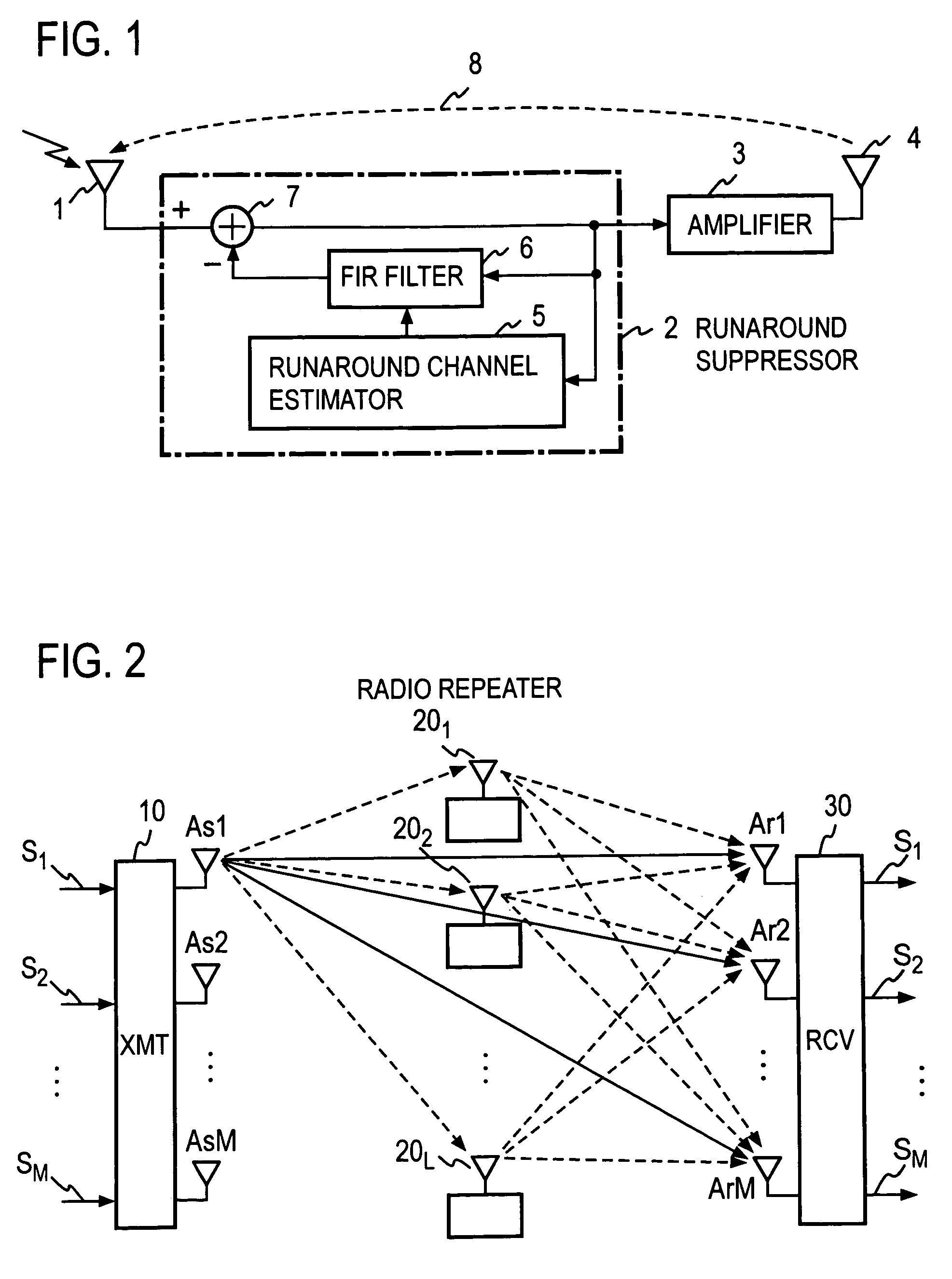
[0056]An exemplary arrangement of a communication system to which the mode 2 can be applied is schematically shown in FIG. 8. A transmitter 10 is provided with a first-polarization and a second-polarization transmission antenna 111 and 112 having polarizations which are orthogonalized. Radio signals on a common frequency band are simultaneously transmitted from the first-polarization and the second-polarization transmission antenna 111 and 112. Information series S1 and S2 which are transmitted as radio signals from the first-polarization and the second-polarization transmission antenna 111 and 112, may be similar or dissimilar.

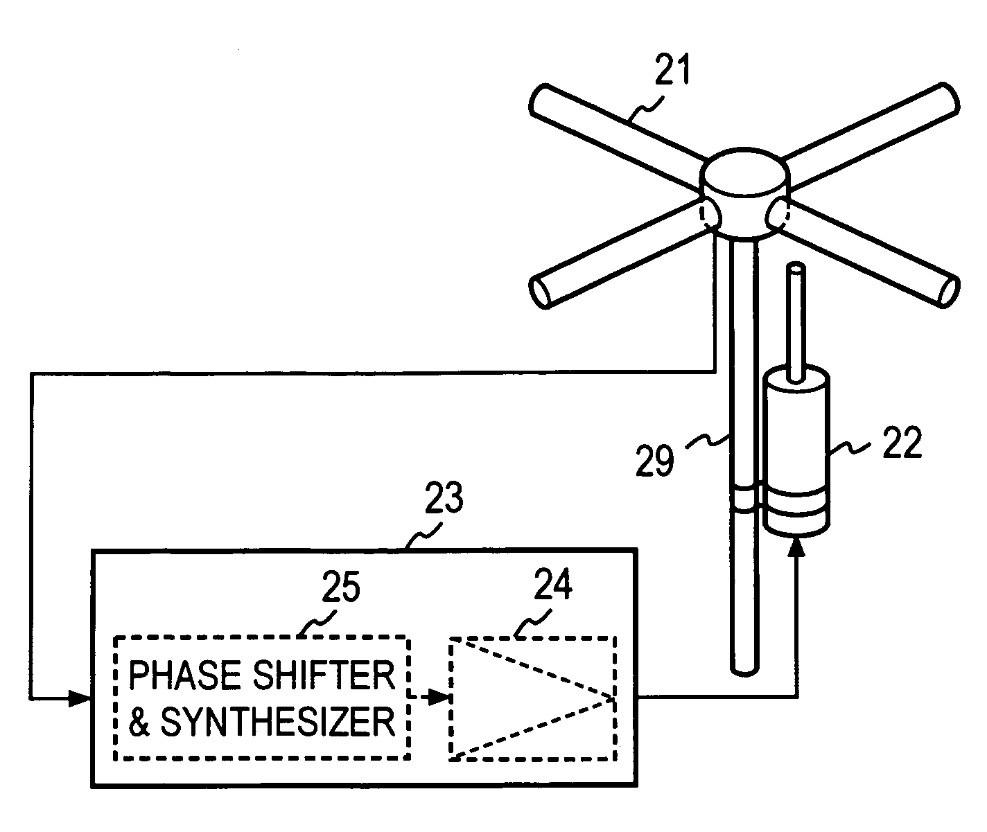
[0057]A radio repeater 20 is provided with a first-polarization reception antenna 21 having the same polarization characteristic of one of the first-polarization and the second-polarization antenna 111 and 112 which is the polarization characteristic of the transmission antenna 111 in the example shown, and with a second-polarization transmission antenna 22 h...

system example 2

[0064]A system arrangement to which the radio relay transmission method according to the present invention can be applied will be described with reference to FIG. 9 which illustrates the system arrangement in a simplified form.

[0065]A radio signal is transmitted from a first-polarization transmission antenna 11 of a transmitter 10 and is received by a first-polarization reception antenna 21 of a radio repeater 20 which has the same polarization characteristic as the first-polarization transmission antenna 11. The received radio signal is amplified and is transmitted from a second-polarization transmission antenna 22 having a polarization characteristic which is orthogonalized to the reception antenna 21 or is transmitted as a radio signal having a polarization which is orthogonalized to the polarization of the received radio signal. In a receiver 30, the radio signal is received by a second-polarization reception antenna 311 having the polarization characteristic which is identical ...


PUM


Abstract

A radio repeater including at least first and second relay systems, each including a reception antenna configured to receive a radio signal, a loop interference suppressor, connected to the reception antenna, configured to suppress a loop interference signal in the received radio signal from said reception antenna, an amplifier configured to amplify the loop interference-suppressed radio signal from the loop interference suppressors, and a transmission antenna having a polarization characteristic, which is orthogonal to a polarization characteristic of said reception antenna, configured to transmit the output of said amplifier.

Description

TECHNICAL FIELD[0001]The present invention relates to a radio relaying in a general radio communication system, and in particular, to a radio repeater and a radio relay transmission method suitable for use in a radio relaying in a mobile radio communication system.BACKGROUND ART[0002]In a conventional radio relay transmission method, a transmitter transmits a radio signal having a vertical polarization, for example, and a radio repeater receives the radio signal transmitted from the transmitter and amplifies the received radio signal to be transmitted as a radio signal having a vertical polarization toward a receiver. Thus the radio repeater amplifies the received radio signal and transmits it as a radio signal having the same polarization as the polarization of the received radio signal. Consequently, the receiver receives the radio signal having the same polarization as the polarization of the radio signal transmitted by the transmitter.[0003]In such a radio repeater, a reception ...

Claims


Application Information

Patent Timeline
Patent Type & Authority Patents(United States)
IPC IPC(8): H04B3/36H04B7/14H04B7/155H04B7/26
CPCH04B7/15564
Inventor SUDA, HIROHITOASAI, TAKAHIROFUJII, HIROMASATANAKA, TETSU
Owner NTT DOCOMO INC
Why Eureka
Try Eureka