Image acquiring device and method capable of performing optimum time lapse imaging easily

a time lapse imaging and image acquisition technology, applied in the direction of fluorescence/phosphorescence, exposure control, instruments, etc., can solve the problems of operation errors, difficult for the operator to select the imaging method, and variable contradictory states, so as to avoid the contradiction of the time elapse imaging condition

Inactive Publication Date: 2008-10-07
OLYMPUS CORP
View PDF5 Cites 11 Cited by
  • Summary
  • Abstract
  • Description
  • Claims
  • Application Information

AI Technical Summary

Benefits of technology

[0079]avoiding condition generating means for generating a plurality of time lapse imaging conditions for avoiding the contradiction of the time lapse imaging condition based on the determined result by the determining means, and causing to present information relating to the plurality of time lapse imaging conditions by the presenting means;
[0096]According to the invention described above, when there is a contradiction of an imaging condition in time elapse imaging, at least information relating to the contradiction of the time elapse imaging condition is presented to an operator, and further an imaging method by a plurality of time elapse imaging conditions for avoiding the contradiction of the time elapse imaging condition is presented. Therefore, the operator can avoid the contradiction of the time elapse imaging condition and select an optimum imaging method easily.

Problems solved by technology

However, if the exposure time Tc is intended to be included in the imaging interval Tb designated by the operator, various contradictory states may result.
Generally, however, in time lapse imaging, the important item differs with the purpose of photography, such as photography with emphasis on the exposure time or photography with emphasis on the imaging interval, and such limitation by the UI makes it difficult for the operator to select the imaging method, or is likely to lead to operation errors.

Method used


Image

  • Image acquiring device and method capable of performing optimum time lapse imaging easily
  • Image acquiring device and method capable of performing optimum time lapse imaging easily
  • Image acquiring device and method capable of performing optimum time lapse imaging easily

Examples


first embodiment

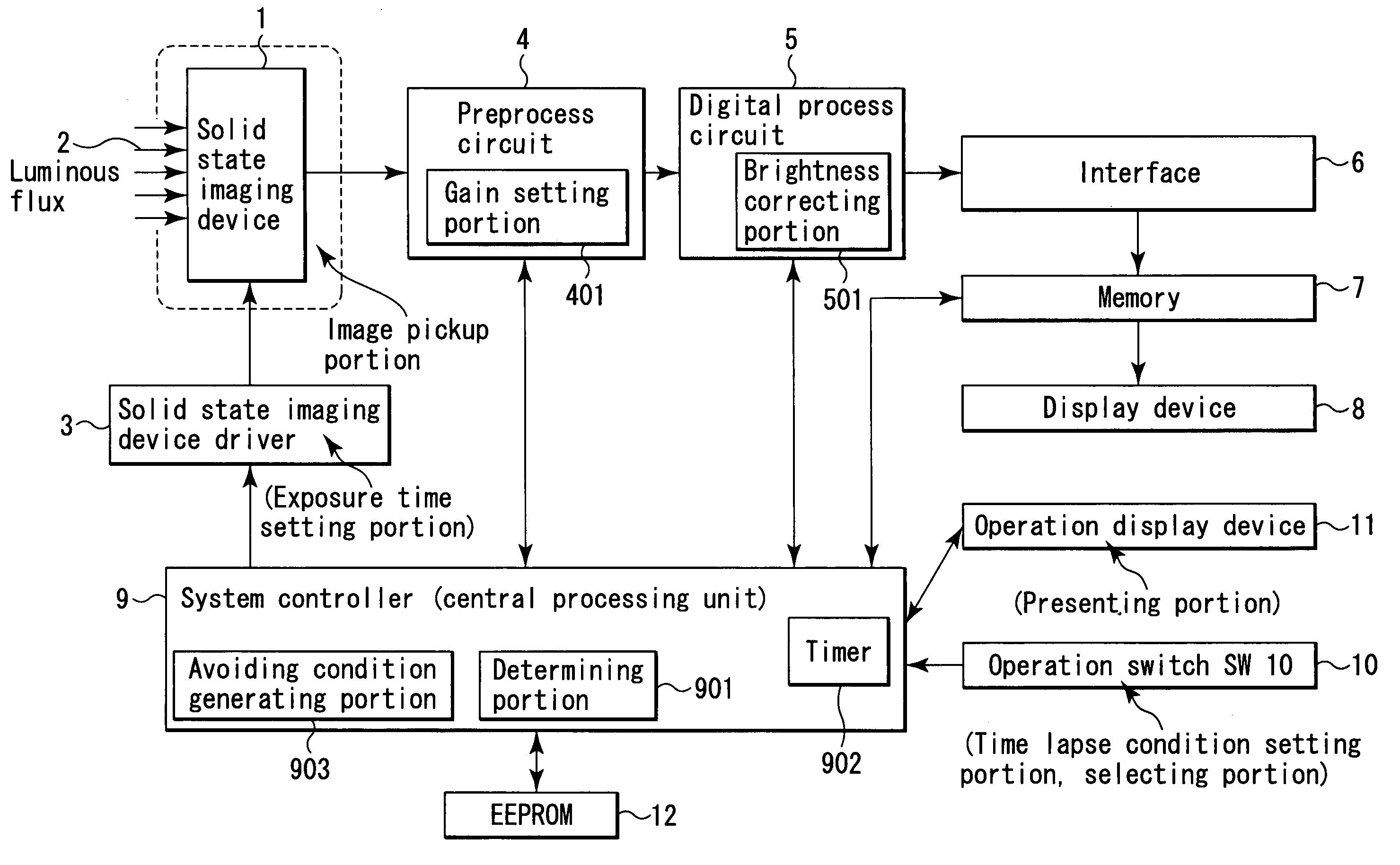
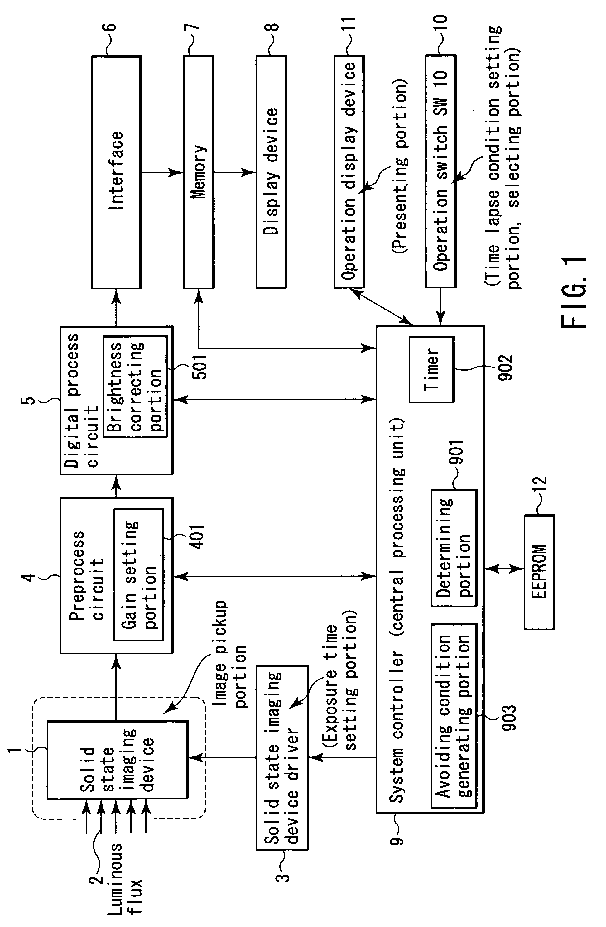
[0113]FIG. 1 is a block diagram showing a schematic configuration of a microscopic image acquiring device which is applied as an image acquiring device for performing time lapse imaging according to a first embodiment of the invention.

[0114]In FIG. 1, reference numeral 1 is a solid state imaging device such as a CCD as an imaging portion (means) of the microscopic image acquiring device for fluorescence photography.

[0115]In such a microscopic image acquiring device, for example, when taking time course changes of live cells, an exposure time is often very long, from several seconds to tens of seconds, in order to image the subject of an extremely low luminance by fluorescence photography.

[0116]On the imaging plane of the solid state imaging device 1, a luminous flux 2 of an observed image of the subject (not shown) is entered.

[0117]A solid state imaging device driver 3 for generating a timing signal is connected to the solid state imaging device 1 as exposure time setting means.

[011...

second embodiment

[0223]An image acquiring device for performing time lapse imaging according to a second embodiment of the present invention will be described below.

[0224]The configuration itself of a microscopic image acquiring device of the second embodiment is same as in FIG. 1, and the following explanation is based on FIG. 1 and its description.

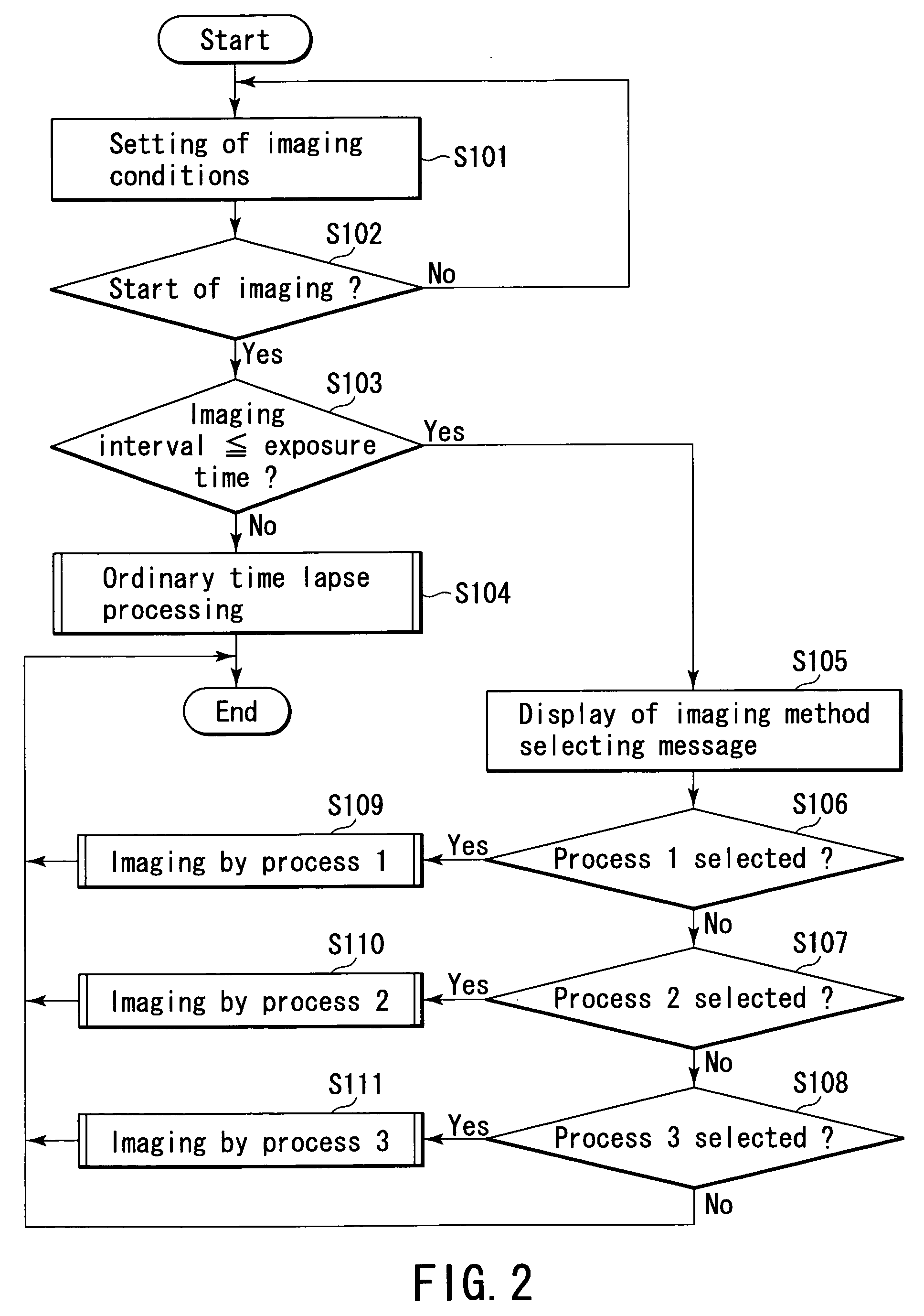
[0225]The second embodiment is a process corresponding to a modified example of “process 2” mentioned in the first embodiment.

[0226]The process corresponding to the modified example of “process 2” is a process selected when the operator desires to take pictures by giving priority to the imaging interval same as in the first embodiment.

[0227]In this case, too, if the exposure time is changed to a shorter time than the imaging interval, the taken image becomes darker by the portion of the shortness of the exposure time.

[0228]The sensitivity is raised by correcting the brightness of the taken image by the brightness correcting portion 501 of the digital pro...

third embodiment

[0243]An image acquiring device for performing time lapse imaging according to a third embodiment of the present invention will be described below.

[0244]The configuration itself of a microscopic image acquiring device of the third embodiment is same as in FIG. 1, and the following explanation is based on FIG. 1 and its description.

[0245]The third embodiment is a combination of“process 2” in the first embodiment, and a process corresponding to a modified example of “process 2” in the first embodiment.

[0246]That is, in “process 2” in the first embodiment, the gain coefficient to be set in the preprocess circuit 4 is determined from the relation of the shortened exposure time and the imaging interval.

[0247]However, if the difference between the imaging interval and the shortened exposure time is large, the obtained gain coefficient may be larger than the gain coefficient that can be set in the preprocess circuit 4 (hereinafter called maximum gain), so that it may not be sufficient for ...


PUM

PropertyMeasurementUnit
time lapse imagingaaaaaaaaaa
exposure timeaaaaaaaaaa
imagingaaaaaaaaaa

Abstract

An imaging portion performs imaging of a subject. A time lapse imaging condition setting portion sets a time lapse imaging condition including at least an exposure time and an imaging interval, prior to the imaging of the subject by the imaging portion. A determining portion determines a contradiction of the time lapse imaging condition set by the time lapse imaging condition setting portion according to a predetermined criterion. A presenting portion presents at least information relating to the contradiction of the time lapse imaging condition based on a determined result by the determining portion.

Description

CROSS-REFERENCE TO RELATED APPLICATIONS[0001]This application is based upon and claims the benefit of priority from the prior Japanese Patent Application No. 2003-022359, filed Jan. 30, 2003, the entire contents of which are incorporated herein by reference.BACKGROUND OF THE INVENTION[0002]1. Field of the Invention[0003]The present invention relates to an image acquiring device and method for performing a time lapse imaging function, and more particularly to an image acquiring device and method having a time lapse imaging function capable of selecting an optimum imaging method easily.[0004]2. Description of the Related Art[0005]Hitherto is known an image acquiring device having a time lapse imaging function for taking and recording images automatically at specific time intervals, and, for example, an imaging device (digital still camera) disclosed in Patent Document 1 (Jpn. Pat. Appln. KOKAI Publication No. 11-112852) is known.[0006]Such an imaging device having a time lapse imaging...

Claims


Application Information

Patent Timeline
Patent Type & Authority Patents(United States)
IPC IPC(8): H04N7/18G03B17/18G03B7/083H04N5/222H04N5/225H04N5/228H04N9/47G03B7/093G01N21/64G02B21/36G03B17/40G06T1/00H04N5/232H04N5/235
CPCG01N21/6458H04N5/232H04N5/23222H04N5/2353H04N23/60H04N23/64H04N23/73
Inventor UEDA, HITOSHI
Owner OLYMPUS CORP
Why Eureka
Try Eureka