Laser surveying instrument

a technology of laser surveying and laser beam, which is applied in the direction of instruments, distance measurement, reference lines/planes/sectors, etc., can solve the problems of complicated mechanism, complicated structure of the mechanism, and difficulty in achieving the effect of simple construction

Active Publication Date: 2008-10-07
KK TOPCON
View PDF4 Cites 12 Cited by
  • Summary
  • Abstract
  • Description
  • Claims
  • Application Information

AI Technical Summary

Benefits of technology

[0012]It is an object of the present invention to provide a laser surveying instrument, which is simple in construction and which can set and tilt the laser reference plane as desired and can attain high tilt setting accuracy and high reproducibility.
[0014]According to the present invention, a laser surveying instrument is provided, which comprises a laser projector for projecting a laser beam by rotary irradiation and designed as tiltable, a tilting unit for tilting the laser projector, a rotating unit for integrally rotating the tilting unit and the laser projector in horizontal direction, a tilt setting unit for tilting the laser projector with respect to the rotating unit and for setting a target tilt angle, a tilt angle detector for detecting tilting of the laser projector, tilt sensors provided on the tilt setting unit in two directions perpendicularly crossing and for detecting horizontal direction, a horizontal angle detector for detecting horizontal rotation angle of the rotating unit, and an arithmetic control unit for controlling rotation angle of the rotating unit based on detection results of the tilt sensors and based on detection results of the horizontal angle detector. As a result, a tilt reference plane can be set by a laser surveying instrument designed in simple construction.

Problems solved by technology

However, in the laser surveying instrument of the former case, the tilt setting mechanisms are needed respectively for two tilting directions, and the mechanism has complicated structure.
There is a problem that the accuracy of the setting angle may be affected, when mechanical components are worn out and the like as time elapses.
While problems lie in that complicated mechanism is required because tilt setting mechanisms are needed for two tilting directions respectively.

Method used


Image

  • Laser surveying instrument
  • Laser surveying instrument
  • Laser surveying instrument

Examples


Embodiment Construction

[0021]Detailed description will be given below on the best mode for carrying out the present invention referring to the attached drawings.

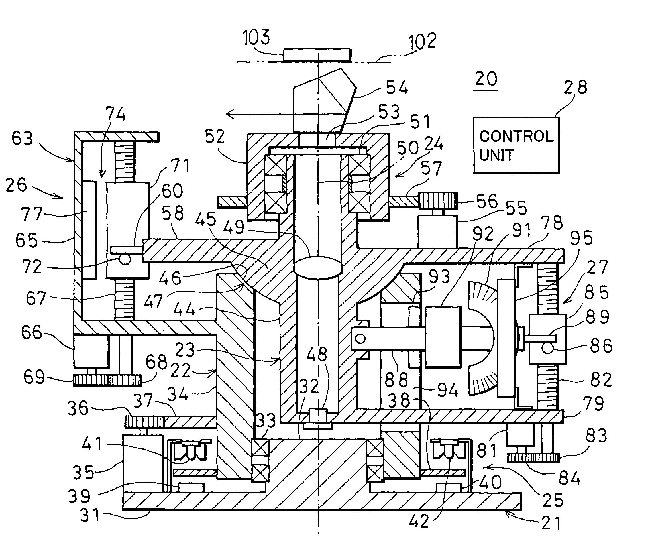
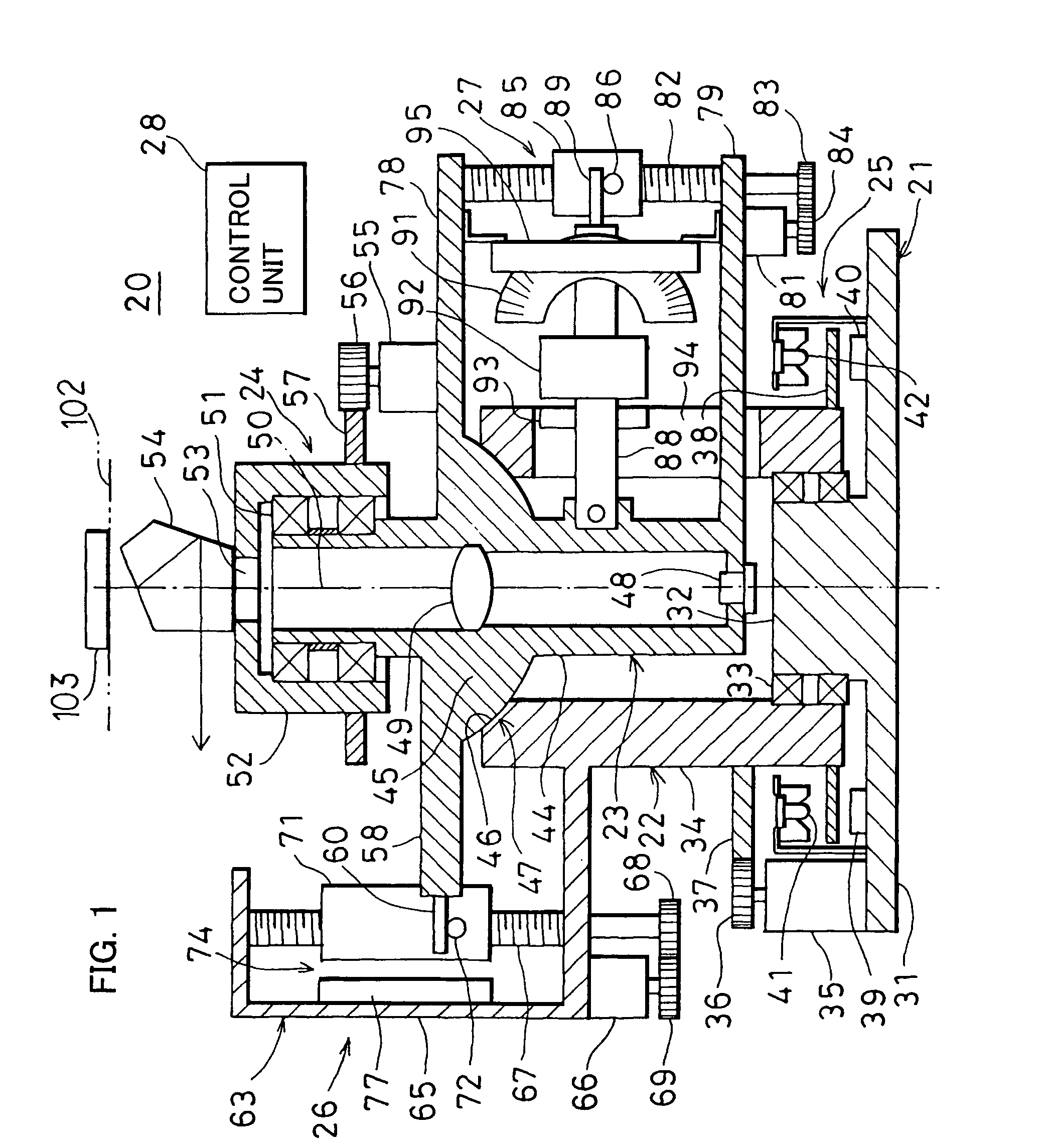
[0022]Now, description will be given on a laser surveying instrument 20 of the present invention by referring to FIG. 1 and FIG. 2.

[0023]The laser surveying instrument 20 primarily comprises a base unit 21, a rotating unit 22 rotatably mounted on the base unit 21, a laser projector 23 tiltably mounted on the rotating unit 22, a rotary irradiation unit 24 rotatably provided on upper end of the laser projector 23, a horizontal angle detector 25 arranged between the base unit 21 and the rotating unit 22, a tilting unit 26 provided between the rotating unit 22 and the laser projector 23, a tilt setting unit 27 provided on the laser projector 23, a control unit 28, and an operation unit 30. Mechanical components unit including the rotating unit 22, the laser projector 23, the rotary irradiation unit 24, the tilt setting unit 27, etc. are accommodated i...


PUM


Abstract

A laser surveying instrument, comprising a laser projector for projecting a laser beam by rotary irradiation and designed as tiltable, a tilting unit for tilting the laser projector, a rotating unit for integrally rotating the tilting unit and the laser projector in horizontal direction, a tilt setting unit for tilting the laser projector with respect to the rotating unit and for setting a target tilt angle, a tilt angle detector for detecting tilting of the laser projector, tilt sensors provided on the tilt setting unit in two directions perpendicularly crossing and for detecting horizontal direction, a horizontal angle detector for detecting horizontal rotation angle of the rotating unit, and an arithmetic control unit for controlling rotation angle of the rotating unit based on detection results of the tilt sensors and based on detection results of the horizontal angle detector.

Description

BACKGROUND OF THE INVENTION[0001]The present invention relates to a laser surveying instrument for forming a horizontal plane or a tilted plane as desired by projecting a laser beam by rotary irradiation.[0002]Reference lines and reference planes are indispensable in the execution of construction work and civil engineering work, and the reference line and plane are formed as the result of projection of the laser beam by rotary irradiation. In the past, a laser surveying instrument has been known, which can form a horizontal reference plane and also can form a tilt reference plane with a desired tilt angle, and such surveying instrument is described in JP-A-6-26861 or in JP-A-2001-280964.[0003]The laser surveying instrument 10 as disclosed in JP-A-6-26861 comprises, as shown in FIG. 5, a projector 1 for projecting a laser beam 13 by rotary irradiation and tiltable in two directions, 2 sets of tilting mechanisms 2 for tilting the projector 1 in two directions, 2 sets of fixed tilt det...

Claims


Application Information

Patent Timeline
Patent Type & Authority Patents(United States)
IPC IPC(8): G01B11/26
CPCG01C15/004
Inventor KUMAGAI, KAORUKODAIRA, JUN-ICHI
Owner KK TOPCON
Why Eureka
Try Eureka