System linking apparatus for generated electric power

a technology of system linking and generated electric power, which is applied in the control system, dc-ac conversion without reversal, electric generator control, etc., can solve the problems of large conduction loss and switching loss, large switching loss, and difficulty in effectively obtaining energy, so as to achieve the effect of reducing the size and facilitating the operation

Active Publication Date: 2008-10-07
FUJI ELECTRIC CO LTD +1
View PDF8 Cites 38 Cited by
  • Summary
  • Abstract
  • Description
  • Claims
  • Application Information

AI Technical Summary

Benefits of technology

[0016]The present invention is made in consideration of those respects, and it is an object of the present invention to provide a system linking apparatus for a generated electric power which may be constructed in smaller size and more efficiently by including a magnetic energy regenerating circuit.

Problems solved by technology

This kind of problem about the system linkage is disclosed in the Official Gazette of Japanese Patent No. 2897208.
In general, therefore, a highly endurable semiconductor device brings about a larger conduction loss and switching loss than a low endurable semiconductor.
These power losses bring about a difficulty in effectively obtaining energy.
Hence, the PWM rectifier 9 disadvantageously brings about a larger switching loss and makes the system linking apparatus larger in size and more costly.

Method used


Image

  • System linking apparatus for generated electric power
  • System linking apparatus for generated electric power
  • System linking apparatus for generated electric power

Examples


Embodiment Construction

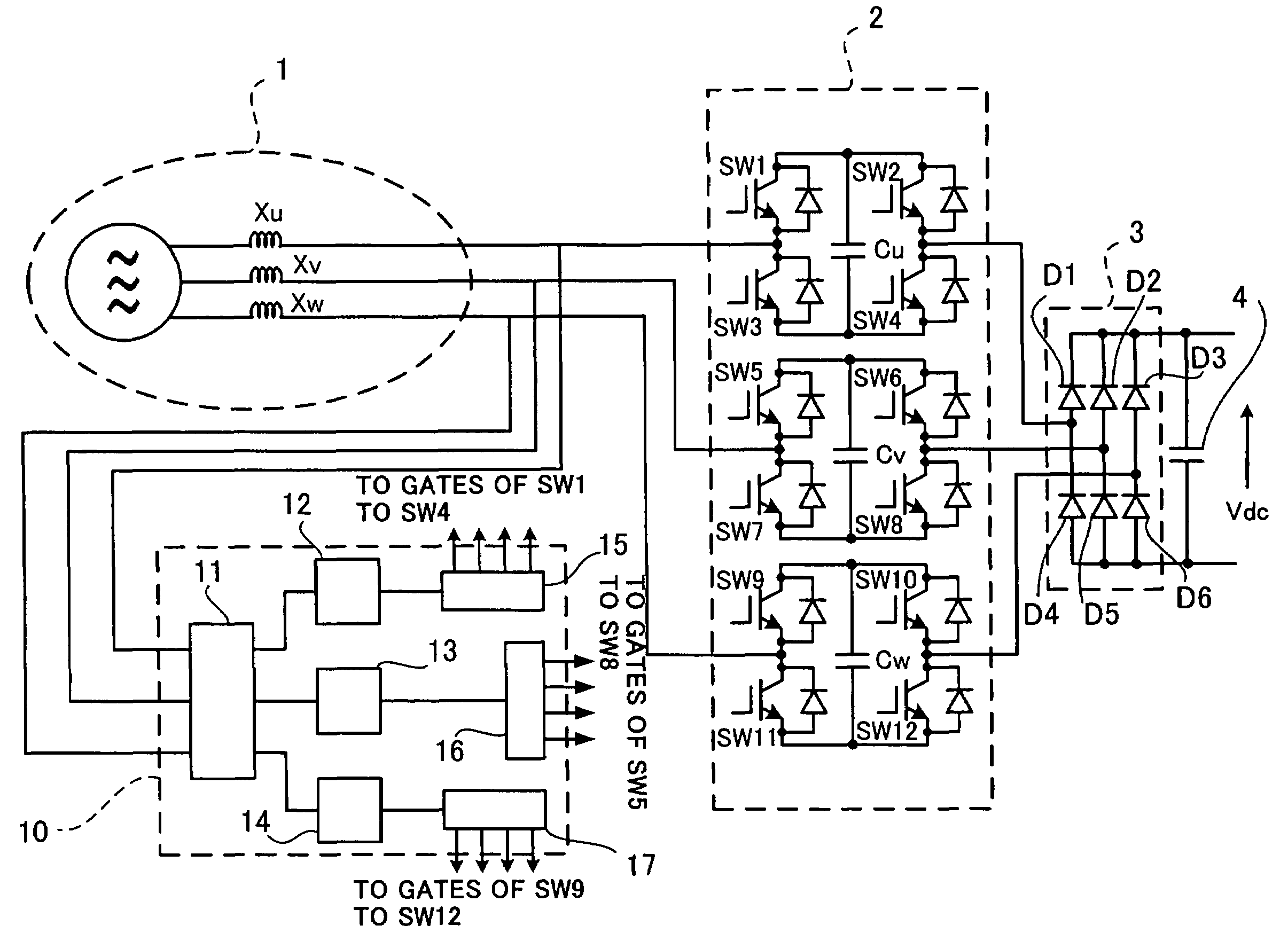
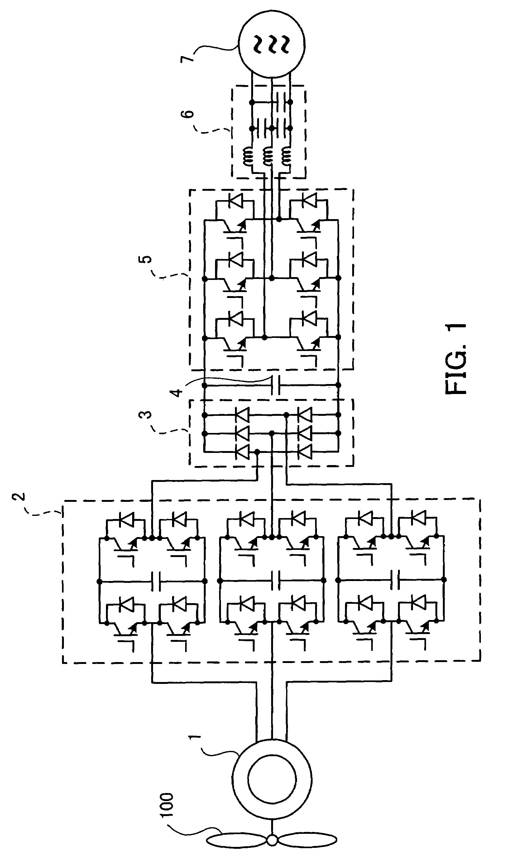
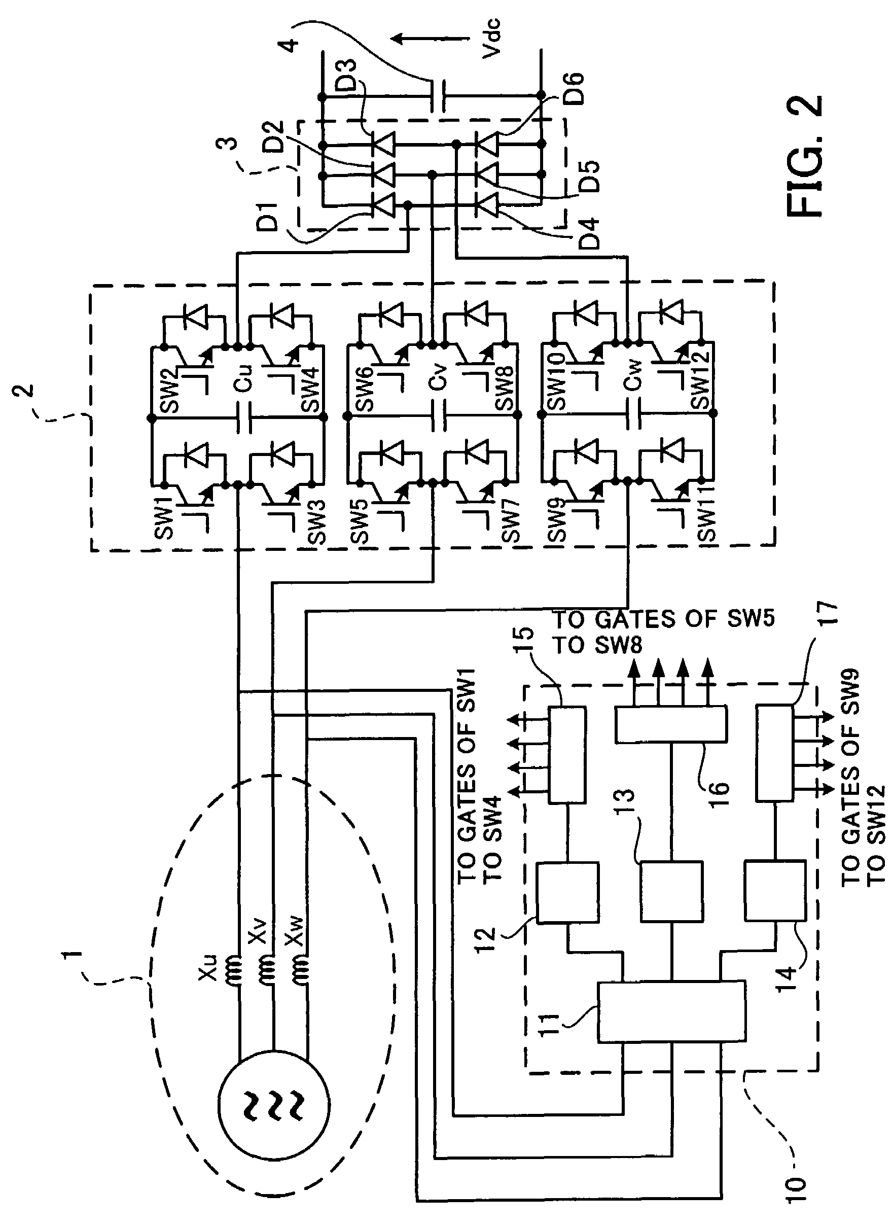
[0027]Hereafter, the embodiment of the present invention will be described with reference to the appended drawings. FIG. 1 is a circuit diagram showing a system linking apparatus according to an embodiment of the present invention.

[0028]It is assumed that the system linking apparatus shown in FIG. 1 includes as a power generator 1 a synchronous generator directly driven by the rotation of a propeller 100. The output of the synchronous generator is connected with an electric power system 7 through a PWM inverter 5 served as a linking inverter. The difference between this system linking apparatus and the apparatus shown in FIG. 4 is as follows. First, instead of the PWM rectifier 9, a diode rectifier 3 composed of four diodes D1 to D6 is used. Second, a magnetic energy regenerating circuit 2 is located between the power generator 1 and the diode rectifier 3. The magnetic energy regenerating circuit 2 is made up of bridge circuits each of which is composed of four of reverse-conducting...


PUM


Abstract

A system linking apparatus for generated electric power which may be made smaller and more efficient. The system linking apparatus is intended for connecting an electric power system to an output of a power generator through a linking inverter (PWM inverter). The system linking apparatus includes a magnetic energy regenerating circuit, a diode rectifier, and a capacitor. The magnetic energy regenerating circuit has a capacitor for condensing magnetic energy condensed in the power generator. The diode rectifier is connected with the magnetic energy regenerating circuit and operates to dc convert electric power generated by the power generator and output the converted power to the linking inverter. The capacitor is connected with the diode rectifier and operates to keep a dc output to the linking inverter at a predetermined voltage.

Description

CROSS-REFERENCE TO RELATED APPLICATIONS[0001]This application is based upon and claims the benefits of priority from the prior Japanese Patent Application No. 2004-329624, filed on Nov. 12, 2004, the entire contents of which are incorporated herein by reference.BACKGROUND OF THE INVENTION[0002](1) Field of the Invention[0003]The present invention relates to a system linking apparatus for generated electric power which is constructed to connect an electric power system to an output side of a power generator through a linking inverter. More particularly, the present invention relates to the system linking apparatus for generated electric power which does not suffer from increase of a current capacity of a converting device resulting from an inferior power factor caused by leakage inductance of a power generator.[0004](2) Description of the Related Art[0005]Recently, aero generation that utilizes inexhaustible and regenerative energy, that is, wind power is rapidly prevailing worldwide...

Claims


Application Information

Patent Timeline
Patent Type & Authority Patents(United States)
IPC IPC(8): H02M5/45H02J3/38H02M5/458H02M7/48H02P9/00
CPCH02M5/4585
Inventor IGARASHI, SEIKIUCHIDA, YOSHIYUKISHIMADA, RYUICHI
Owner FUJI ELECTRIC CO LTD
Why Eureka
Try Eureka