Optical cross connect apparatus and network

a cross-connecting and optical technology, applied in the field of optical cross-connecting apparatuses, can solve the problems of inability to determine the state of the incorrect connection, the conventional line exchange apparatus does not monitor the state of all, and the conventional misconnection detection method does not provide means, so as to avoid the state of the wrong communication speed in advance, avoid the effect of incorrect connection and reducing the frequency of system maintenan

Inactive Publication Date: 2008-10-07
HITACHI LTD
View PDF13 Cites 6 Cited by
  • Summary
  • Abstract
  • Description
  • Claims
  • Application Information

AI Technical Summary

Benefits of technology

[0024]One feature of the present embodiment provides a method of monitoring a state of inter-user connection through a plurality of nodes such as optical cross connect apparatus for switching and connecting large-capacity transmission lines on physical layers (layers 1) by using a network management apparatus 37 in a concentrated manner in a process of setting transmission lines in the optical cross connect apparatus represented by the aforementioned OXC apparatus and the aforementioned OADM. It is another object of the present invention to provide a method of determining whether or not a connection on not only the physical layers but also layers higher than the physical layers is possible. It is a further object of the present invention to provide a method of reporting the state of an incorrect connection to the person in charge of system maintenance as a state of incorrect line exchange setting made by the person. That is to say, it is an object of the present invention to provide means for avoiding incorrect line setting (or an incorrect connection) that would otherwise link mutually incompatible user signals on the physical layer in advance and means for reporting a result of determination to the person in charge of system maintenance. The mutually incompatible user signals are user signals having attributes, which include data formats and / or protocols, different from each other on the physical layer and layers higher than the physical layer.
[0028]The optical cross connect apparatus for handling a variety of high-velocity and broadband optical communication lines used in the optical cross connect system is provided with a function for cataloging the type of each signal used in networks connected to input / output ports employed in the optical cross connect apparatus and a function for recognizing connectability or determining whether or not a connection is possible prior to actual connection of these networks. Accordingly, it is possible to avoid an incorrect connection between signals having different services and / or different protocols beforehand as well as avoid a state of mismatching communication speeds in advance. Incorrectly connected large-capacity transmission lines would have a bad effect on a service provided by the transmission lines. With such an optical cross connect apparatus, however, such an effect can be reduced to a minimum. In addition, the networks can be prevented from being operated in the state of an incorrect connection. Thus, unlike the conventional optical cross connect system, a maintenance work caused by an incorrect connection of networks is no longer required. As a result, the frequency of the system maintenance can be decreased. In particular, the method provided by the present invention is effective for an apparatus and a system, which are used for handling a variety of diverse large-capacity transmission lines having different kinds, without regard to the velocity and protocol type of a signal propagating through each of the transmission lines.

Problems solved by technology

Thus, with the conventional misconnection detection methods, an incorrect connection cannot be determined till the lines are actually connected to each other.
That is to say, the conventional misconnection detection methods do not provide means for avoiding such a state of an incorrect connection in advance before setting lines.
That is to say, these conventional line exchange apparatus do not monitor the state of all connections of lines serving as routes for user signals between input points and output points in a concentrated manner.

Method used


Image

  • Optical cross connect apparatus and network
  • Optical cross connect apparatus and network
  • Optical cross connect apparatus and network

Examples


first embodiment

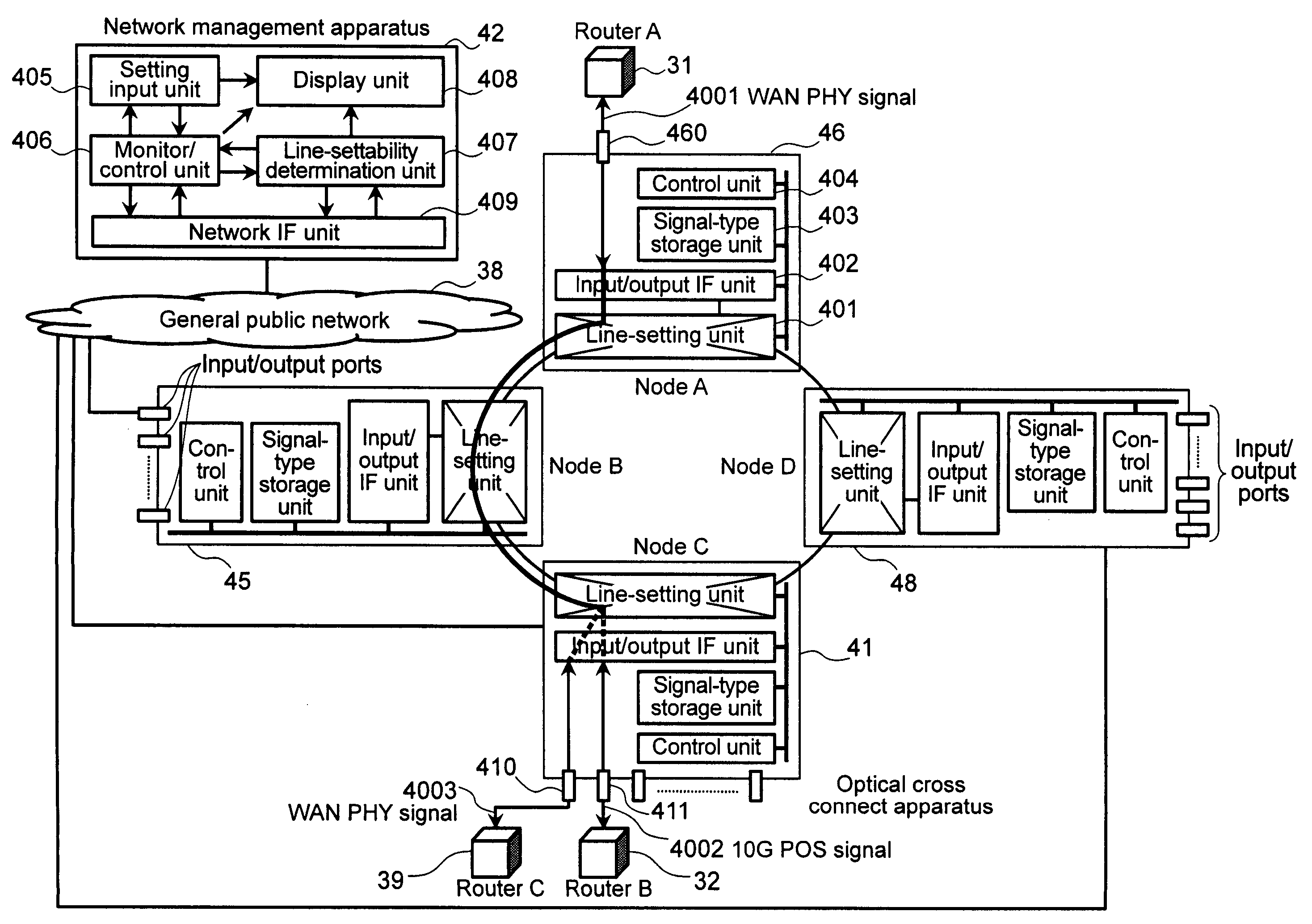
[0057]FIG. 4 is a diagram showing a system configuration of a first embodiment implementing an optical cross connect system comprising optical cross connect apparatus and a network management apparatus, which are provided by the present invention. More specifically, the optical cross connect system is constituted of nodes A46, B45, C41 and D48, which are the optical cross connect apparatus and linked to each other to form a ring-shaped connection, and a network management apparatus 42 for monitoring and controlling the nodes. The network management apparatus 42 is connected to the nodes by a general public network 38 such as DCN (Data Communication Network) lines provided by a communication carrier company to monitor and control the nodes from a remote location. It is to be noted that the network management apparatus 42 can also be directly connected to the nodes without using the general public network 38. As another alternative, the network management apparatus 42 can also be conn...

second embodiment

[0084]FIG. 7 is a diagram showing a system configuration of a second embodiment implementing an optical cross connect system comprising optical cross connect apparatus and a network management apparatus, which are provided by the present invention, in the same configuration as the first embodiment. More specifically, the optical cross connect apparatus of the optical cross connect system implemented by the embodiment are nodes A76, B75, C71 and D78 linked to each other to form a ring-shaped connection, and the network management apparatus 72 is used for monitoring and controlling the nodes. The network management apparatus 72 is connected to the nodes A76, B75, C71 and D78 by a general public network 38 to monitor and control the nodes from a remote location. In this system, a physical port e411 of the node C71 is connected to a router B32, which serves as a terminal using a 10G POS signal. On the other hand, a physical port a460 of the node A76 is connected to a router A31 serving ...

third embodiment

[0093]FIG. 8 is a diagram showing a system configuration of a third embodiment implementing an optical cross connect system comprising optical cross connect apparatus and a network management apparatus, which are provided by the present invention, in the same configuration as the first and second embodiments. The optical cross connect apparatus of the optical cross connect system implemented by the embodiment are nodes A86, B85, C81 and D88 and the network management apparatus 72 is used for monitoring and controlling the nodes.

[0094]FIG. 17 is a diagram showing the configuration of the node A86 employed in this embodiment. The configuration of the node A includes both the signal-type storage unit 403 employed in the first embodiment and the signal-type recognition unit 700 employed in the second embodiment. The configuration of the optical cross connect system as a whole is the same as those of the first and second embodiments shown in FIGS. 4 and 7 respectively. In addition, the i...


PUM


Abstract

An optical signal connection apparatus includes first and second routers configured to handle optical signals and electrical signals. A first node includes a first port coupled to the first router and is configured to handle a first type of optical signals associated with the first route; a first line-setting unit configured to couple the first and second nodes for data communication between the first and second nodes; a first control unit to control setting an optical communication link between the first and second nodes; and a first signal-type storage unit. A second node includes a second port coupled to the second router and configured to handle a second type of optical signals, wherein the first information is compared with second information on the second type of optical signal to determine whether the first and second communication links are compatible to each other.

Description

CROSS-REFERENCES TO RELATED APPLICATIONS[0001]The present application claims priority to Japanese Patent Application No. 2004-016463, filed on Jan. 26, 2004.BACKGROUND OF THE INVENTION[0002]The present invention relates to an optical cross connect apparatus used in an optical transmission system as an apparatus for switching large-capacity lines on an optical layer and adding / dropping such lines. The invention further relates to a network management apparatus for monitoring and controlling the optical cross connect apparatus.[0003]In recent years, broadband lines have been becoming popular also at homes and the demand for the broadband lines for mainly handling IP traffic has been rapidly increasing. Transmission apparatus for handling such a variety of high-speed lines include an OXC (optical cross connect) apparatus and an OADM (Optical Add-Drop Multiplexer). The OXC apparatus has an optical cross connect function for switching routes between a plurality of input / output ports pass...

Claims


Application Information

Patent Timeline
Patent Type & Authority Patents(United States)
IPC IPC(8): H04J3/00H04L12/26G02B6/35H04B10/07H04B10/079H04B10/27H04J3/08H04J3/12H04J3/16H04J14/00H04J14/02H04L12/24H04L29/06H04Q11/00
CPCH04J3/12H04J3/1617H04J14/0283H04L41/12H04J14/0241H04J3/085H04J14/0227H04L41/08H04L41/34
Inventor ATSUMI, TOSHIYUKISHIBASAKI, MASATOSHITAKANO, TERUHISA
Owner HITACHI LTD
Why Eureka
Try Eureka