Optical network and optical add/drop apparatus

a technology which is applied in the field of optical network and optical add/drop apparatus, can solve the problems of high cost, complex node architecture, and large scale of devices that structure nodes, and achieve the effect of simple and compact configuration, low cost and low cos

Active Publication Date: 2008-10-07
FUJITSU LTD
View PDF11 Cites 12 Cited by
  • Summary
  • Abstract
  • Description
  • Claims
  • Application Information

AI Technical Summary

Benefits of technology

[0042]According to the invention, it is possible to connect the plurality of nodes on the optical network at a low cost with a simple and compact configuration.

Problems solved by technology

In this type of network architecture, respective nodes connected directly to the backbone network and the individual nodes connected to the sub-networks were incapable of performing communications without any restrictions.
Therefore, a node architecture became complicated, and devices that structure the nodes came to a large scale and were expensive.
Hence, this network was hard to be built up in the metropolitan area having a small amount of allowable space.
In this case, each node has a necessity of setting the respective optical function components in linkage, which involves complicated control.
The full-mesh network was therefore difficult to be actualized at a low cost.
Further, it was also difficult to introduce this network into the metropolitan area having the small amount of allowable space.
The conventional drop filter had, however, a case of being unable to completely removing the light having a drop target wavelength from the wavelength division multiplexed light.
Hence, this system required extremely a high-band WDM amplifier for amplifying the wavelength division multiplexed light traveling across the optical network, resulting in a high cost for building up the network.[Patent document 1] Japanese Patent Application Laid-Open Publication No. 11-218790[Patent document 2] Japanese Patent Application Laid-Open Publication No. 2002-214473

Method used


Image

  • Optical network and optical add/drop apparatus
  • Optical network and optical add/drop apparatus
  • Optical network and optical add/drop apparatus

Examples


first embodiment

[0062]A first embodiment of the invention will be explained with reference to the drawings in FIGS. 5 through 12. Herein, the embodiment of the invention will be discussed by exemplifying an optical ring network. FIG. 5 is a view of a configuration of the optical ring network according to the embodiment. As shown in FIG. 5, the optical ring network includes an optical network medium (which will hereinafter be called a fiber 1) that builds up a ring-configured connection, through which an optical signal flows unidirectionally, and a plurality of nodes #1-#N connected to the fiber 1. In the case of individually identifying each node, the nodes are referred to as the node #1, the node #2, etc. and are, when generically termed, simply called the node. The node includes an optical add / drop multiplexer (multi / demultiplexer) 3 corresponding to an optical add drop apparatus that adds the optical signal to the fiber 1 or demultiplexes the optical signal from the optical fiber 1 (see FIG. 6)....

second embodiment

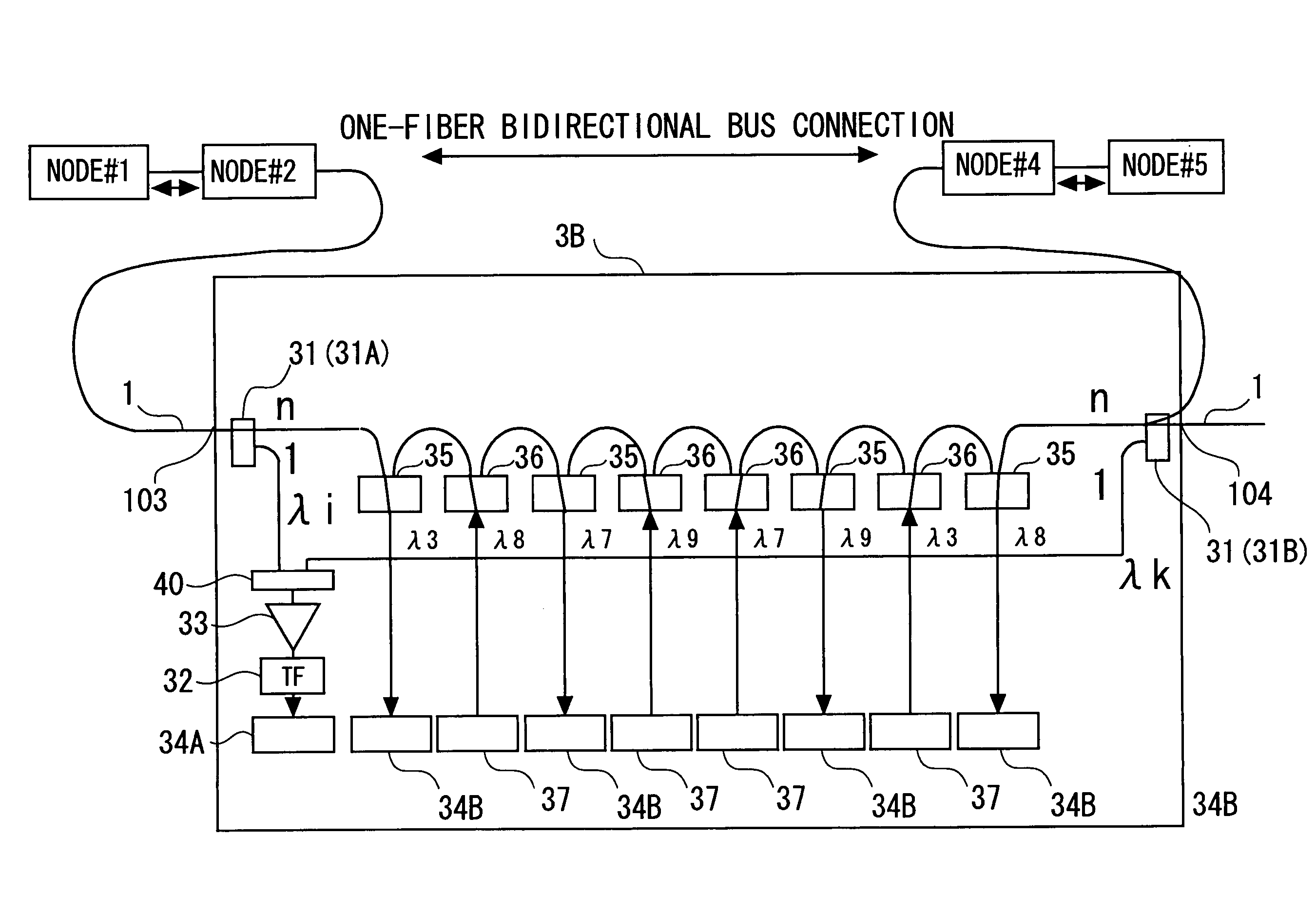
[0121]A second embodiment of the invention will be described with reference to FIGS. 13 through 15. The first embodiment has shown the example, wherein the node on the optical ring network is constructed by use of the plurality of fixed wavelength drop filters 35, the plurality of fixed wavelength add filters 36 and one or more optical tunable filters 32. Further, in the first embodiment, the optical signal of the wavelength that is received by each node on the optical ring network is reused, and the multicast distribution is actualized by the optical signal of the wavelength used for the communication with the node existing in the remotest position in topology of the optical ring network from the node concerned.

[0122]In the second embodiment, an optical network taking a bus type is configured by use of the plurality of fixed wavelength drop filters 35, the plurality of fixed wavelength add filters 36 and one or more optical tunable filters 32. In this case, unlike the node configur...

third embodiment

[0157]A third embodiment of the invention will be described with reference to FIGS. 16 through 18. The first embodiment has exemplified how the optical ring network is configured, in which the optical add / drop multiplexers 3 including the fixed wavelength drop filters 35 and the fixed wavelength add filters 36 serve as the nodes.

[0158]By the way, in the case of altering the network in a way that adds or removes the nodes, it is required that the fixed wavelength drop filters 35 and the fixed wavelength add filters 36 be added to all the nodes (the removal is not necessarily required). In this case, maintainability is improved by taking a unit form (which is also called a module form), wherein the respective filters 35, 36 are set paired. Such being the case, the third embodiment will exemplify an example of constructing the optical add / drop multiplexer 3 by using the paired units of the fixed wavelength drop filters 35 and the fixed wavelength add filters 36. Other configurations an...


PUM


Abstract

Provided are a plurality of fixed wavelength drop filters 35 demultiplexing optical signals having a plurality of different fixed wavelengths, a plurality of fixed wavelength add filters 36 provided corresponding respectively to the fixed wavelength drop filters 35 and adding the optical signals having the fixed wavelengths wavelength division multiplexed light flowing along a transmission path 1, a first optical branching unit 31 branching part of the wavelength division multiplexed light flowing along the transmission path 1, and a variable wavelength drop filter 32 demultiplexing the optical signal having the wavelength corresponding to a specified value from the wavelength division multiplexed light branched by the first optical branching unit 31.

Description

BACKGROUND OF THE INVENTION[0001]The invention relates to an optical network and an optical add / drop apparatus used in the optical network.[0002]At the present, in an optical network (which is also called a photonic network), there increases importance of a function “optical add / drop (OADM: Optical Add / Drop Multiplexer)” of dropping and adding a flux of signal light having a specified wavelength from signal light subjected to wavelength division multiplexing (WDM) in an optical node (refer to, e.g., Patent documents 1 and 2).[0003]A conventional typical network is configured by a high-speed backbone network and lower-speed sub-networks connected to the backbone network. In this type of network architecture, respective nodes connected directly to the backbone network and the individual nodes connected to the sub-networks were incapable of performing communications without any restrictions. For example, each node connected directly to the backbone network is at first required to be co...

Claims


Application Information

Patent Timeline
Patent Type & Authority Patents(United States)
IPC IPC(8): H04J14/02H04J14/00H04B10/00H04B10/2507H04B10/27H04B10/275H04B10/278H04B10/29
CPCH04J14/0206H04J14/0209H04J14/021H04J14/0283H04J14/0238H04J14/0204H04J14/0213H04J14/0227H04J14/028H04J14/0284
Inventor KAI, YUTAKA
Owner FUJITSU LTD
Why Eureka
Try Eureka