Exhaust device for vehicle engine

a technology for exhaust devices and vehicles, applied in the direction of shock absorbers, instruments, heat measurement, etc., can solve the problems of increasing noise due to the vibration of the heat insulating cover, and the exhaust device tends to vibrate, so as to suppress the generation of noise

Active Publication Date: 2008-10-14
HONDA MOTOR CO LTD
View PDF61 Cites 34 Cited by
  • Summary
  • Abstract
  • Description
  • Claims
  • Application Information

AI Technical Summary

Benefits of technology

[0007]It is accordingly a first embodiment of the present invention an exhaust device for a vehicle engine is provided which can suppress the generation of noise from the heat insulating cover for covering a part of the exhaust pipe.
[0008]In an exhaust muffler having a long double pipe structure composed of an inner cylinder and an outer cylinder, there is a case wherein the influence of noise must be considered because the outer cylinder performs the same operation as that of the heat insulating cover. In this case, the outer cylinder is fixed to the inner cylinder in manufacturing the conventional exhaust muffler by plug welding in the condition where a relative position between the outer cylinder and the inner cylinder is hard to confirm. It is therefore necessary to improve the accuracy of positioning between the inner cylinder and the outer cylinder by using a jig or the like in the manufacture, thereby improving a silencing function of the exhaust muffler.
[0009]It is accordingly a second embodiment of the present invention to provide an exhaust device for a vehicle engine which can easily improve the relative positional accuracy between the outer cylinder and the inner cylinder of an exhaust muffler having a double pipe structure to thereby suppress the generation of noise from the exhaust muffler.

Problems solved by technology

Such an exhaust device tends to vibrate due to the exhaust pressure.
Thus, there is a possibility that noise due to the vibrations of the heat insulating cover may be increased.

Method used


Image

  • Exhaust device for vehicle engine
  • Exhaust device for vehicle engine
  • Exhaust device for vehicle engine

Examples


Embodiment Construction

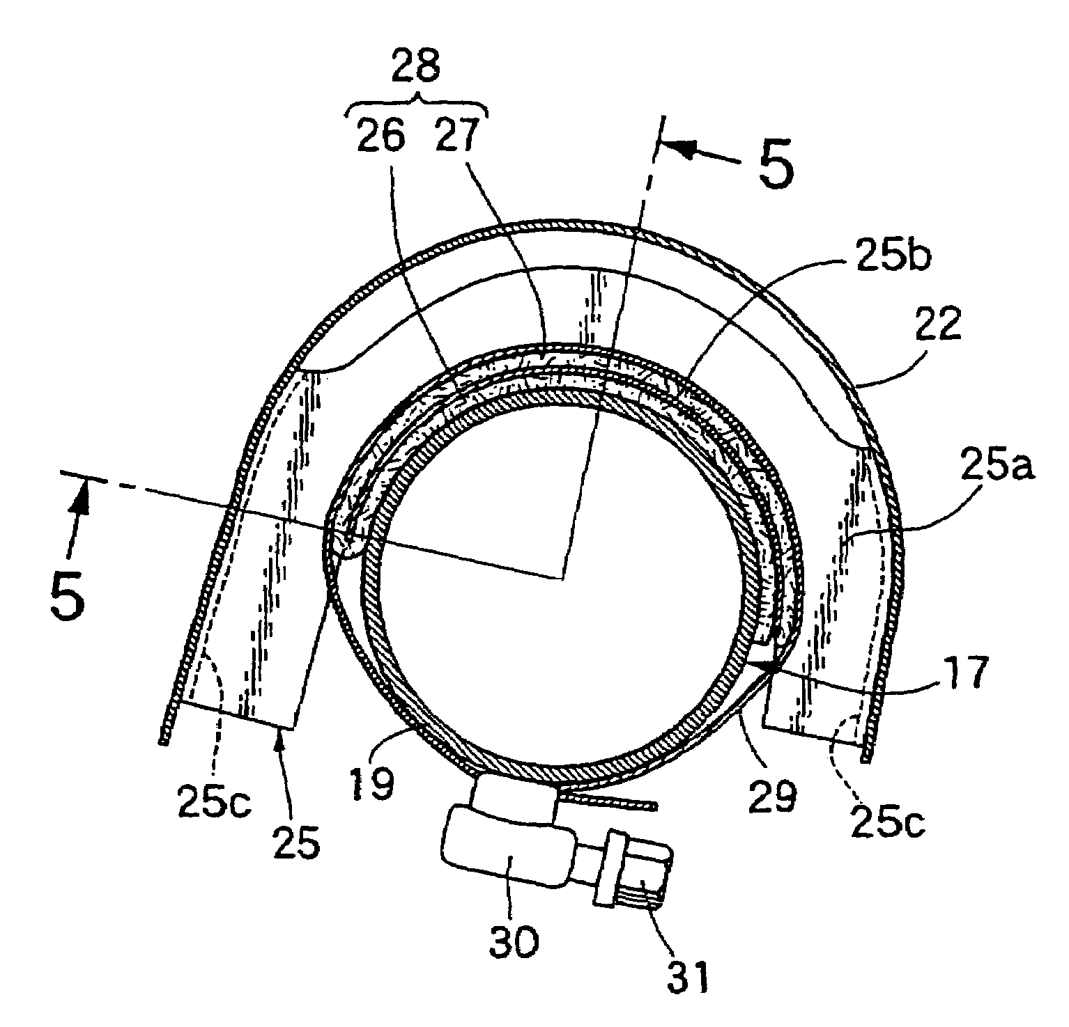
[0039]A preferred embodiment of the present invention will now be described with reference to the attached drawings.

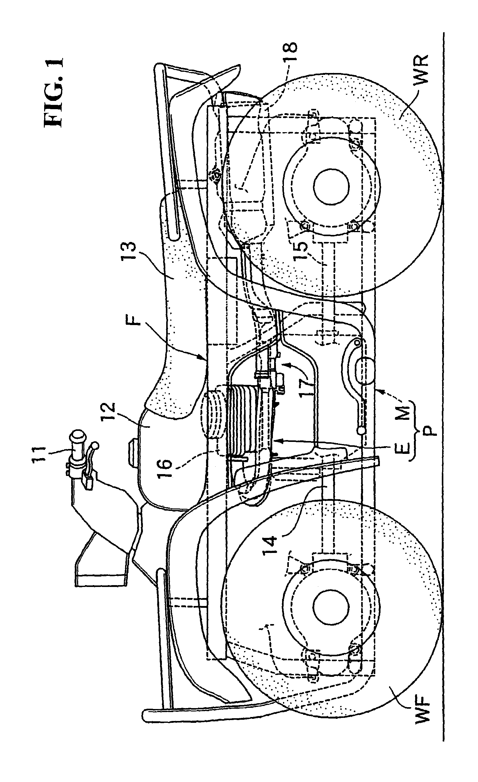
[0040]Referring first to FIG. 1, this saddle seat type vehicle is a four-wheeled buggy for operating on rough terrain, which has a body frame F. A pair of right and left front wheels WF are supported to a front portion of the body frame F, and a pair of right and left rear wheels WR are supported to a rear portion of the body frame F. A steering handle 11, a fuel tank 12, and a saddle type driver's seat 13 are provided on an upper portion of the body frame F so as to be arranged in this order from the front side of the vehicle.

[0041]A power unit P is mounted on the body frame F at its intermediate portion below the fuel tank 12 and the driver's seat 13. The power unit P includes an engine E and a transmission M having a common casing. A drive shaft 14 extends forwardly from the power unit P to transmit power from the power unit P to the right and left front wheels WF, ...


PUM


Abstract

An exhaust device includes an exhaust pipe connected at its upstream end to a cylinder head of the engine and an exhaust muffler connected to the downstream end of the exhaust pipe for suppressing the generation of noise from a heat insulating cover that covers a part of the exhaust pipe. A heat insulating cover covers a portion of the exhaust pipe near the engine and a stay is fixed to the heat insulating cover. The stay includes a supporting plate portion curved so as to partially surround the outer circumference of the exhaust pipe. A first vibration isolating member is provided that is sandwiched between the outer circumference of the exhaust pipe and the supporting plate portion, a band member is tightened to mount the supporting plate portion to the exhaust pipe, and a second vibration isolating member is sandwiched between the supporting plate portion and the band member.

Description

CROSS-REFERENCE TO RELATED APPLICATIONS[0001]The present non-provisional application claims priority under 35 USC 119 to Japanese Patent Application No. 2004-251281 filed on Aug. 31, 2004 the entire contents thereof is hereby incorporated by reference.BACKGROUND OF THE INVENTION[0002]1. Field of the Invention[0003]The present invention relates to an exhaust device for an engine adapted to be mounted on a vehicle, the exhaust device having an exhaust pipe connected at its upstream end to a cylinder head of the engine and an exhaust muffler connected to the downstream end of the exhaust pipe.[0004]2. Description of Background Art[0005]An exhaust device is known as disclosed in Japanese Patent Laid-open No. 2001-123829.[0006]Such an exhaust device tends to vibrate due to the exhaust pressure. In the case when a heat insulating cover is provided for directly covering an exhaust pipe is mounted on the exhaust pipe by using a band as disclosed in Japanese Patent Laid-open No. 2001-123829,...

Claims


Application Information

Patent Timeline
Patent Type & Authority Patents(United States)
IPC IPC(8): F01N7/08F01N13/08F01N13/14F01N13/18
CPCF01N1/24F01N11/00F01N13/1838F01N2470/02Y02T10/47Y02T10/40
Inventor YASUDA, KAZUHIROKOYANAGI, MASASHIABE, SHINTAROYAMAMOTO, KAZUOOSHIMA, TADASHI
Owner HONDA MOTOR CO LTD
Why Eureka
Try Eureka