SAW temperature sensor and system

a temperature sensor and system technology, applied in the direction of heat measurement, acceleration measurement using interia force, instruments, etc., can solve the problems of labor-intensive and intermittent monitoring techniques of patient temperature, and achieve the effect of elegant simplicity and high precision

Active Publication Date: 2008-10-14
SENSANNA
View PDF14 Cites 32 Cited by
  • Summary
  • Abstract
  • Description
  • Claims
  • Application Information

AI Technical Summary

Benefits of technology

[0004]The subject of the present invention is a SAW (surface acoustic wave) temperature sensor and system for remotely sensing temperature with high precision. The system includes a sensor and an interrogator. The sensor is a hermetically sealed SAW device attached to a small antenna. Since there is no power source in or connected to the sensor, it is a completely passive sensor. As such the device is elegantly simple, low-cost, and rugged. A radio frequency (RF) signal is transmitted by the interrogator, received and processed by the sensor, and the modified signal is radiated back to and received by the interrogator. The reflected signal returning from the sensor contains the temperature information. The same reflected signal contains two metrics which specify the temperature for added reliability, i.e., the amplitude and the delay of the reflected signal each independently provide a metric which specifies the temperature. Furthermore, the sensor can be given a unique ID which allows the interrogator to identify and query a large number of sensors individually.

Problems solved by technology

Traditional techniques used to monitor patient temperature were labor intensive and intermittent, relying mainly on hospital personnel to measure patient temperature with standard thermometers.

Method used


Image

  • SAW temperature sensor and system
  • SAW temperature sensor and system
  • SAW temperature sensor and system

Examples


Embodiment Construction

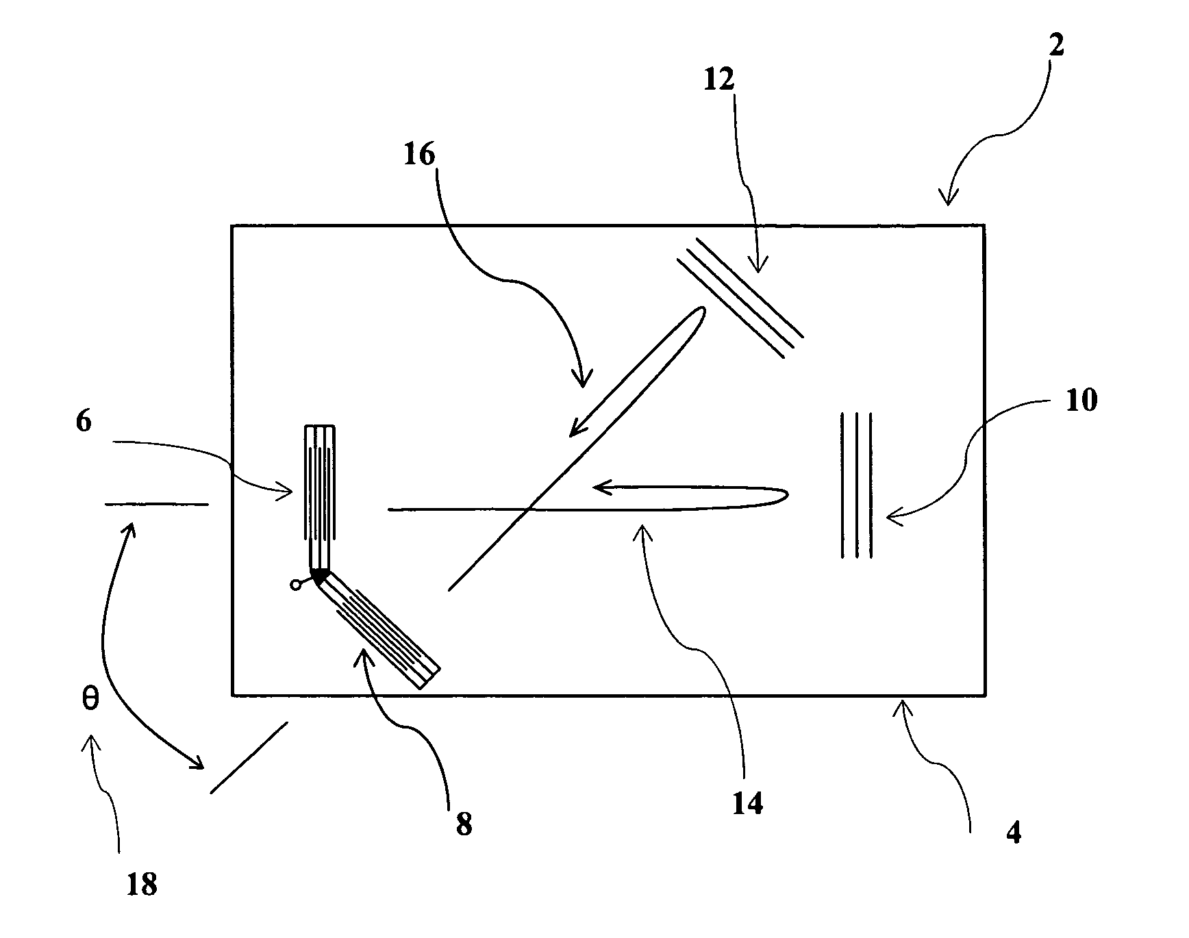
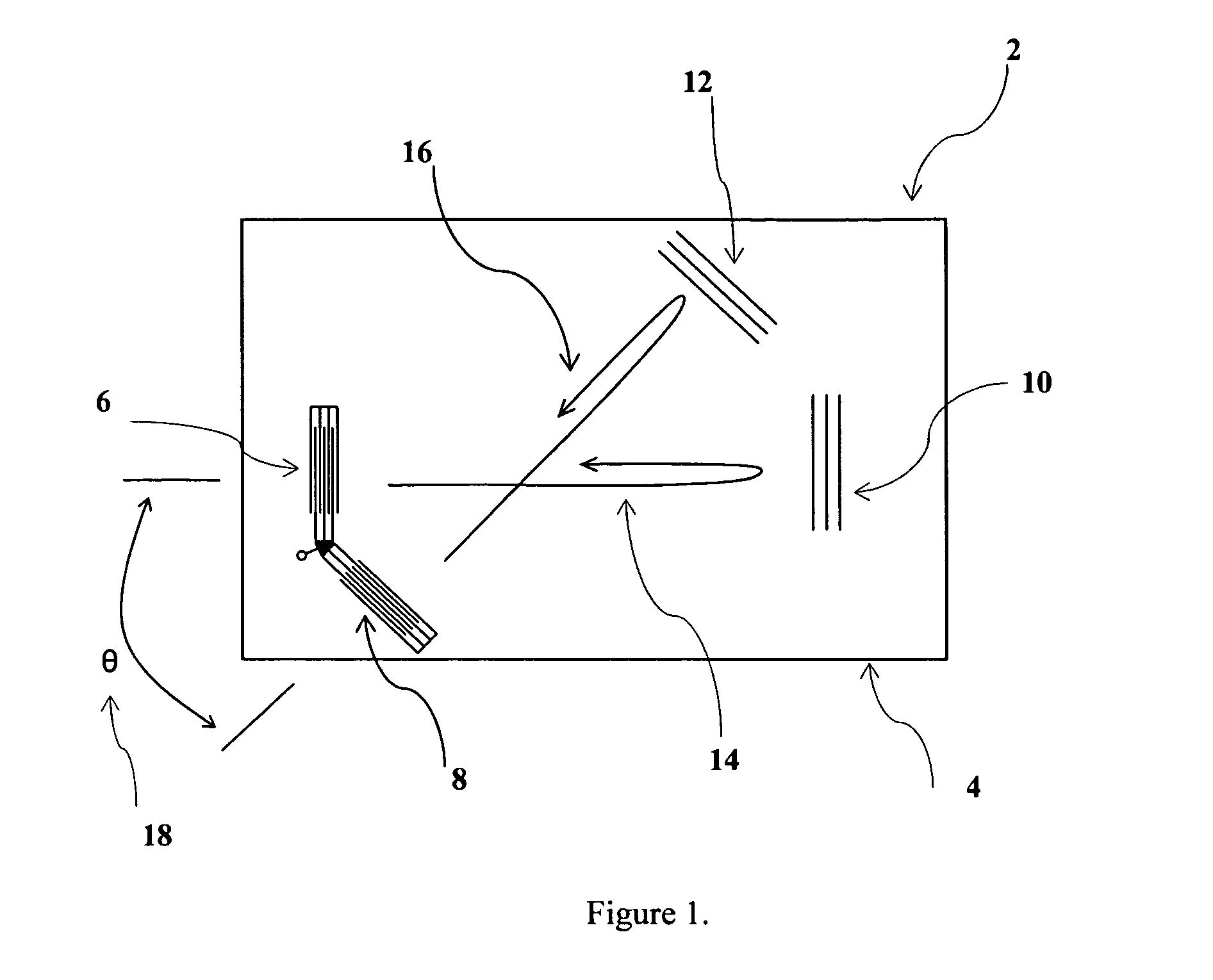
[0018]The preferred embodiment of the present invention will be described with reference to FIG. 1. Shown therein is a SAW device 2 for measuring temperature according to the present invention. The device includes a piezoelectric substrate 4 on which are mounted two SAW transducers 6, 8 and two SAW reflectors 10, 12. These SAW elements are arranged such that they form two non-parallel acoustic tracks, 14 and 16. The angle between these tracks 18 is theta (θ), where θ is greater than zero and is selected for specific desirable properties of the substrate characteristic of the orientations of the two acoustic tracks. Transducers 6 and 8, which are electrically connected in parallel, launch acoustic waves towards reflectors 10 and 12, respectively. The round trip time delay from 6 to 10 and back to 6 is t1, and from 8 to 12 and back to 8 is t2. When designed so that the input transducers are broadband, and the reflector elements 10 and 12 are ideal point (i.e. wide band) reflectors, th...


PUM

PropertyMeasurementUnit
piezoelectric coupling constantaaaaaaaaaa

Abstract

A temperature measurement system is characterized by at least one passive surface acoustic wave (SAW) temperature sensor. The sensor includes at least one piezoelectric substrate having an interdigital SAW transducer disposed upon the piezoelectric substrate for conversion of an RF signal into an acoustic wave and vice versa. At least three additional SAW elements are also disposed on the substrates in a manner such that they define two acoustic propagation paths that are non-parallel relative to the crystal axes of the substrates, and such that the temperature coefficients of delay in the two tracks differ. The SAW elements receive a signal from the SAW transducer and produce response signals. The response signals combine to produce a signal with a power spectral density such that the integrated power within each of two specified portions of the spectrum provides an indicator of the temperature. This change in the power spectral density of the sensor response signal is measured by an interrogator, and yields a measure of the temperature of the sensor.

Description

[0001]This application claims the benefit U.S. provisional application No. 60 / 714,587 filed on Sep. 7, 2005.BACKGROUND OF THE INVENTION[0002]The present invention generally relates to methods and devices for remotely measuring temperature. Measurement of temperature is important for a wide range of applications in almost every field. In many applications, the ability to measure temperature wirelessly provides significant advantages. One such application is the measurement of patient temperature in hospital applications. Traditional techniques used to monitor patient temperature were labor intensive and intermittent, relying mainly on hospital personnel to measure patient temperature with standard thermometers. Recently, radio frequency identification device (RFID) technology has been merged with temperature sensing technology to produce systems capable of remote sensing of temperature. One such system is the “Smart Sense 100” system introduced by Cadi Scientific Pte Ltd. (http: / / www...

Claims


Application Information

Patent Timeline
Patent Type & Authority Patents(United States)
IPC IPC(8): G01K11/22
CPCG01K1/024G01K11/265G01K13/002G01K13/20
Inventor SOLIE, LELAND P.
Owner SENSANNA
Why Eureka
Try Eureka