Phase advance angle optimization for brushless motor control

a brushless permanent magnet motor and phase advance angle technology, applied in the direction of multiple motor speed/torque control, dynamo-electric machines, synchronous motor starters, etc., can solve the problems of limited torque output, prior art does not teach optimizing phase advance angle and phase current amplitude to minimize power consumption, and achieves maximum output torque , minimize phase current, the effect of high degree of precision controllability

Inactive Publication Date: 2008-10-14
MATRA MFG & SERVICES
View PDF18 Cites 46 Cited by
  • Summary
  • Abstract
  • Description
  • Claims
  • Application Information

AI Technical Summary

Benefits of technology

[0034]The present invention fulfills this need, while maintaining the benefits of the separated and ferromagnetically isolated individual stator core element configurations such as disclosed in the copending applications. The ability of the present invention to implement a phase advance angle optimization strategy that maximizes output torque and minimize phase current for individual phase circuit elements offers an optimal torque control strategy for a particular user's requested torque with a higher degree of precision controllability since each phase control loop i...

Problems solved by technology

Hence, the torque output is also limited by power supply constraints.
However, the Henry et al. technique does not produce the values of phase advance angle optimized to achieve the maximum torque output with the minimum phase current.
However, the prior art does not teach optimizing the phase advance angle and the amplitude of phase current to minimize power consumption.
Moreover, a conventional phase advance technique does not pro...

Method used


Image

  • Phase advance angle optimization for brushless motor control
  • Phase advance angle optimization for brushless motor control
  • Phase advance angle optimization for brushless motor control

Examples


Embodiment Construction

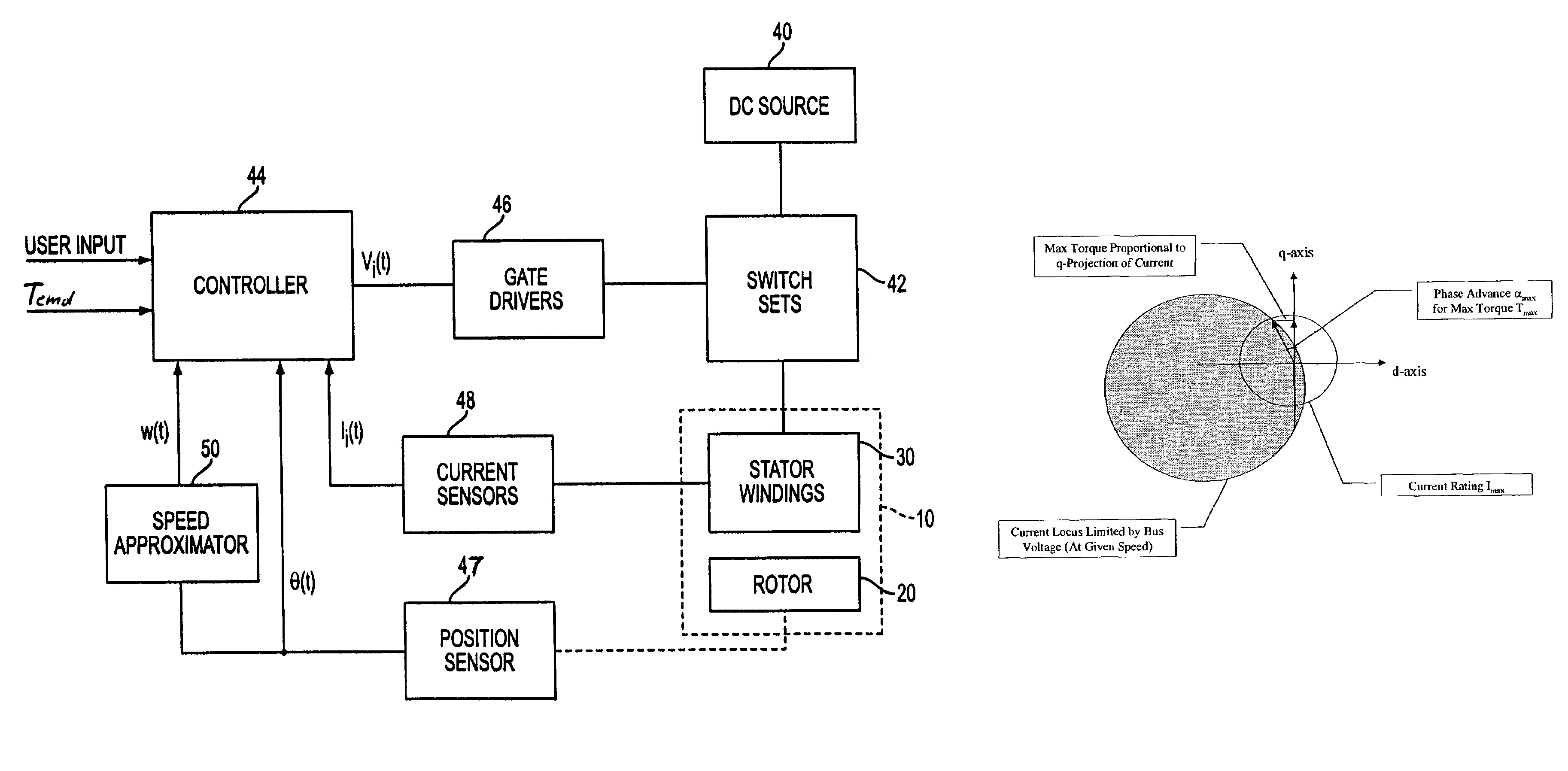
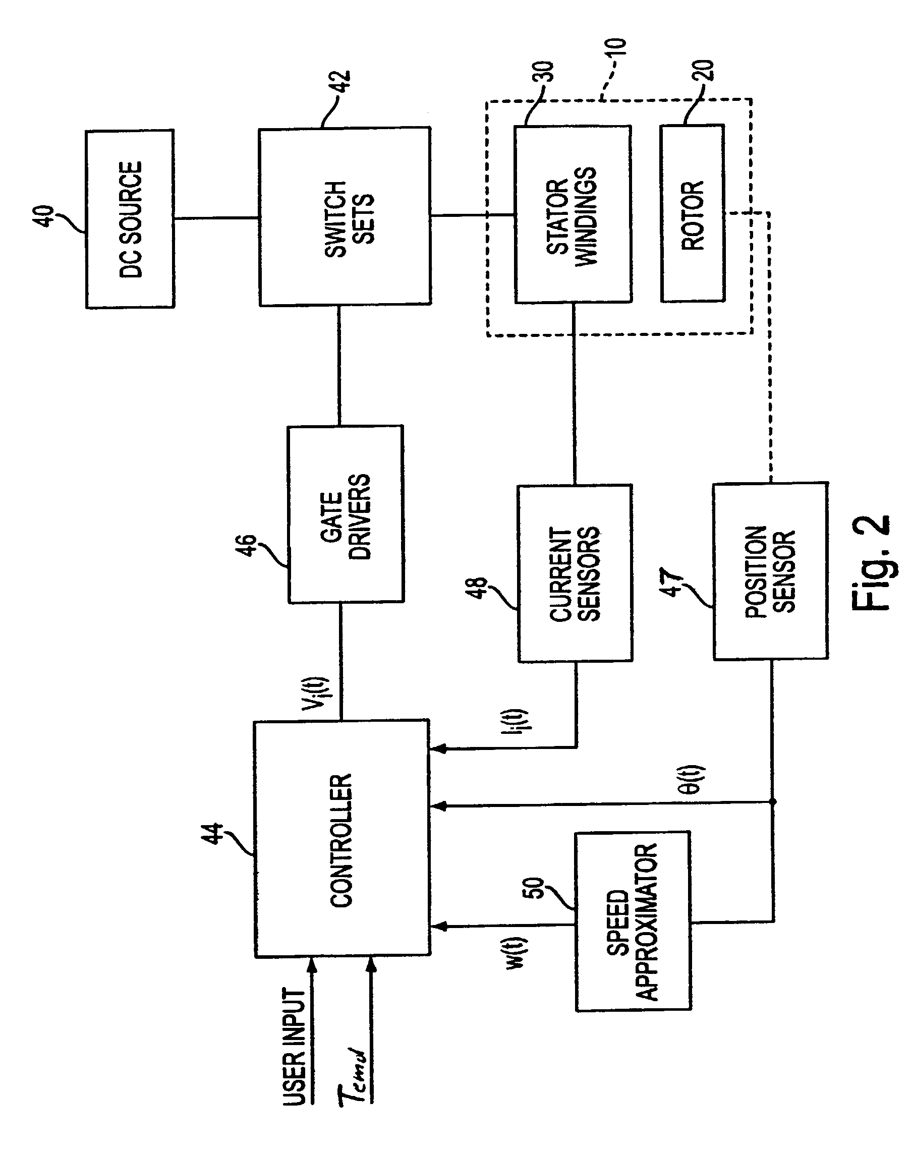
[0059]FIG. 2 is a block diagram of a motor control system in accordance with the present invention. Multiphase motor 10 comprises rotor 20 and stator 30. The stator has a plurality of phase windings that are switchably energized by driving current supplied from DC power source 40 via electronic switch sets 42. The switch sets are coupled to controller 44 via gate drivers 46. Controller 44 has one or more user inputs and a plurality of inputs for motor conditions sensed during operation. Current in each phase winding is sensed by a respective one of a plurality of current sensors 48 whose outputs are provided to controller 44. The controller may have a plurality of inputs for this purpose or, in the alternative, signals from the current sensors may be multiplexed and connected to a single controller input. Rotor position sensor 47 is connected to another input of controller 44 to provide position signals thereto. The output of the position sensor is also applied to speed approximator...


PUM


Abstract

A control system for a multiphase permanent magnet motor having a controller for producing a control signal to energize each phase winding. The controller includes a current value calculator for determining a value of phase current advanced in phase with respect to back-EMF by a phase advance angle, and a phase advance optimization circuit for producing a value of the phase advance angle optimized so as to maximize output torque of the motor and mimimize the phase current. The phase advance optimization circuit determines the phase advance angle optimized for each phase of the motor.

Description

RELATED APPLICATIONS[0001]This application contains subject matter related to copending U.S. application Ser. No. 09 / 826,423 of Maslov et al., filed Apr. 5, 2001, copending U.S. application Ser. No. 09 / 826,422 of Maslov et al., filed Apr. 5, 2001, U.S. application Ser. No. 09 / 966,102, of Maslov et al., filed Oct. 1, 2001, U.S. application Ser. No. 09 / 993,596 of Pyntikov et al., filed Nov. 27, 2001, and U.S. application Ser. No. 10 / 173,610 of Maslov et al., filed Jun. 19, 2002, all commonly assigned with the present application. The disclosures of these applications are incorporated by reference herein.FIELD OF THE INVENTION[0002]The present invention relates to rotary electric motors, and more particularly to phase advance angle optimization for controlling brushless permanent magnet motors.BACKGROUND[0003]The above-identified copending patent applications describe the challenges of developing efficient electric motor drives. Electronically controlled pulsed energization of windings...

Claims


Application Information

Patent Timeline
IPC IPC(8): H02K23/02H02K23/16H02P6/14H02P6/18
CPCH02P6/142H02P6/15H02P6/18
Inventor MASLOV, BORIS A.FEEMSTER, MATTHEW G.YUAN, GUOHUI
Owner MATRA MFG & SERVICES
Why Eureka
Try Eureka