
Method and apparatus for transmitting encoded information based upon priority data in the encoded information

a technology of encoded information and priority data, applied in the field of audiovideo transmitter and audiovideo receiver, data processing apparatus and method, waveformdatatransmitting method and apparatus, can solve the problems of difficult to preponderantly reproduce an important scene cut synchronously with audio, no specific discussion performed, etc., and achieve the effect of keeping the delay small

Inactive Publication Date: 2008-10-14
PANASONIC CORP
View PDF51 Cites 29 Cited by
  • Summary
  • Abstract
  • Description
  • Claims
  • Application Information

AI Technical Summary

Benefits of technology

"The present invention provides an audio-video transmitting apparatus and an audio-video receiving apparatus that can solve various problems related to data transmission, such as overload of transmission lines, limited transmission bandwidth, and inefficient transmission format information. The invention provides a method for transmitting and receiving data using multiplexing control information, which can improve data transmission efficiency and reliability. Additionally, the invention provides a method for dynamically changing transmission format information based on the needs of the receiving apparatus. The technical effects of the invention include improved data transmission efficiency, reliability, and flexibility."

Problems solved by technology

That is, there has been a problem that no specific discussion has been performed from the following viewpoints:
(B1) The conventional method for discussing a picture correspondingly to the frame type of the video has a problem that it is difficult to preponderantly reproduce an important scene cut synchronously with audio by handling a plurality of video streams or a plurality of audio streams and reflecting the intention of an editor because the grading of the information which can be handled is in a single stream.
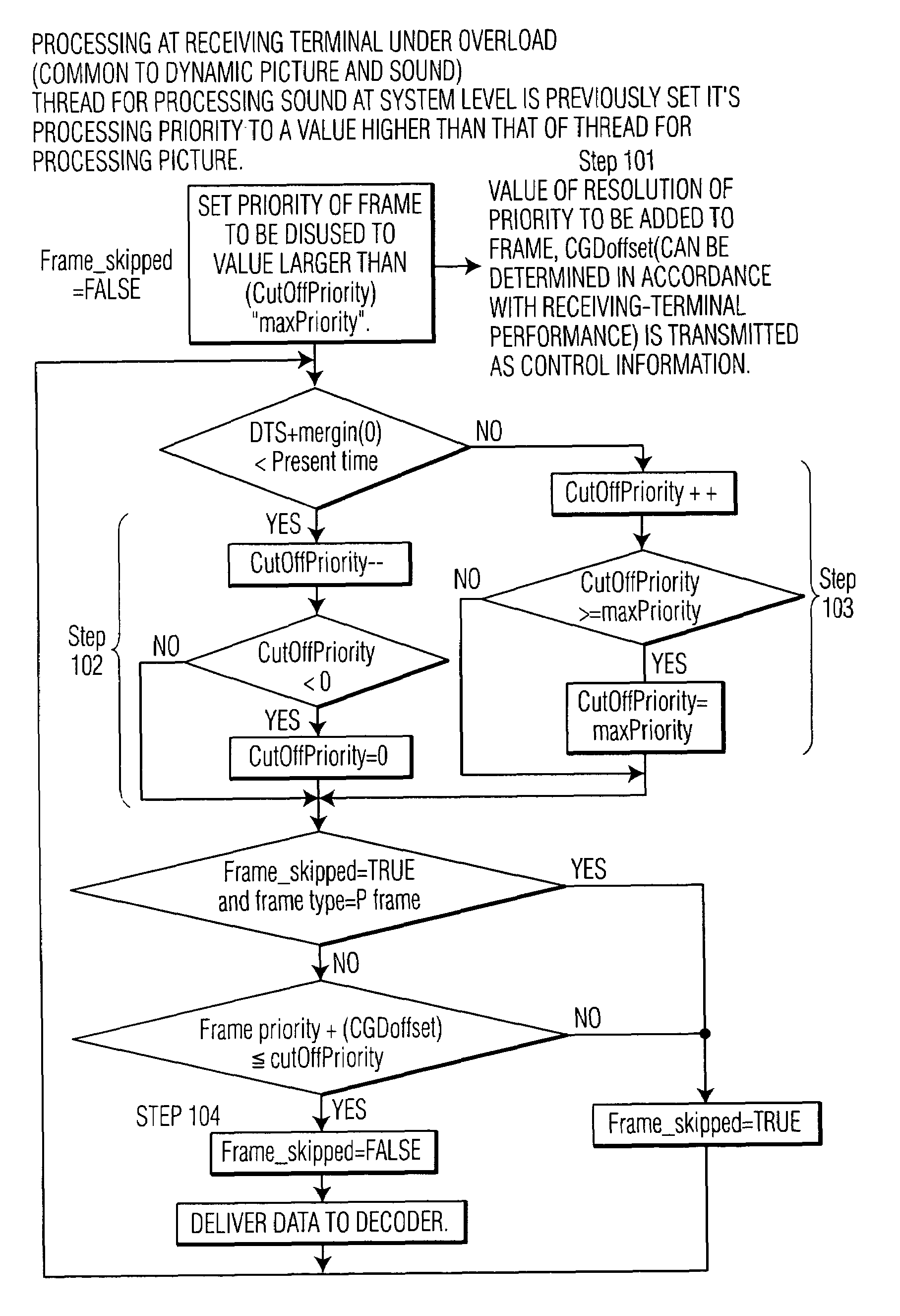
Therefore, it is a problem how to correspond to the case of exceeding the throughput of the decoder.
If decoding is not completed within the time, an extra time becomes a delay.
If the delay is accumulated, the delay from the transmitting side to the receiving side increases and the system cannot be used as a video telephone.
Moreover, when decoding cannot be completed within a designated time because a communication counterpart generates an out-of-spec bit stream, a problem occurs that a video cannot be transmitted.
The above problem occurs not only for a video but also for audio data.
However, because the same software can be executed by personal computers different in structure such as a CPU, bus width, or accelerator, it is difficult to previously consider the upper limit of a necessary performance and therefore, a problem occurs that a picture cannot be decoded within a designated time.
Moreover, when coded data for a video having a length exceeding the throughput of a receiver is transmitted, coding cannot be completed within a designated time.
However, because the last decoded picture is not completely restored by the means for solving the problem 1, there is a problem that deterioration of the picture quality influentially increases as time passes.
Moreover, picture-quality deterioration is spread.

Method used


Image

  • Method and apparatus for transmitting encoded information based upon priority data in the encoded information
  • Method and apparatus for transmitting encoded information based upon priority data in the encoded information
  • Method and apparatus for transmitting encoded information based upon priority data in the encoded information

Examples


first embodiment

[0416]FIG. 33 shows the structure of the transmitter of the Symbol 2101 denotes a picture-input terminal and the size of a sheet of picture has 144 pixels by 176 pixels. Symbol 2102 denotes a video encoder that is constituted with four components 1021, 1022, 1023, and 1024 (see Recommendation H.261).

[0417]Symbol 1021 denotes a switching unit for dividing an input picture into macroblocks (a square region of 16 pixels by 16 pixels) and deciding whether to intra-encode or inter-encode the blocks and 1022 denotes movement compensating means for generating a movement compensating picture in accordance with the local decoded picture which can be calculated in accordance with the last-time encoding result, calculating the difference between the movement compensating picture and an input picture, and outputting the result in macroblocks. Movement compensation includes halfpixel prediction having a long processing time and fullpixel prediction having a short processing time. Symbol 1023 de...

second embodiment

[0421]FIG. 40 is a flowchart of the transmitting method of the

[0422]Because operations of this embodiment are similar to those of the first embodiment, corresponding elements are added. A picture is input in step 801 (picture input terminal 2101) and the picture is divided into macroblocks in step 802. Hereafter, processings from step 803 to step 806 are repeated until the processing corresponding to every macroblock is completed in accordance with the conditional branch in step 807. Moreover, when each processing is executed so that frequencies of the processings from step 803 to step 806 can be recorded in specific variables, a corresponding variable is incremented by 1.

[0423]First, it is decided whether to intra-encode or inter-encode a macroblock to be processed in step 803 (switching unit 1021). When inter-encoding the macroblock, movement compensation is performed in step 804 (movement compensating means 1022). Thereafter, DCT transformation and variable-length encoding are pe...

third embodiment

[0425]FIG. 35 shows the structure of the receiver of the

[0426]In FIG. 35, symbol 307 denotes an input terminal for inputting the output of the transmitter of the first embodiment and 301 denotes receiving means for fetching a variable-length code and a data string through inverse multiplexing in accordance with the output of the transmitter of the first embodiment and outputting them. In this case, it is assumed that the time required to receive the data for one sheet is measured and also output.

[0427]Symbol 303 denotes a decoder for a video using a variable-length code as an input, which is constituted with five components. Symbol 3031 denotes variable-length decoding means for fetching a DCT coefficient and other encoded information from a variable-length code, 3032 denotes inverse orthogonal transforming means for applying inverse DCT transformation to a DCT coefficient, and 3033 denotes a switching unit for switching an output to upside or downside every macroblock in accordance...


PUM


Abstract

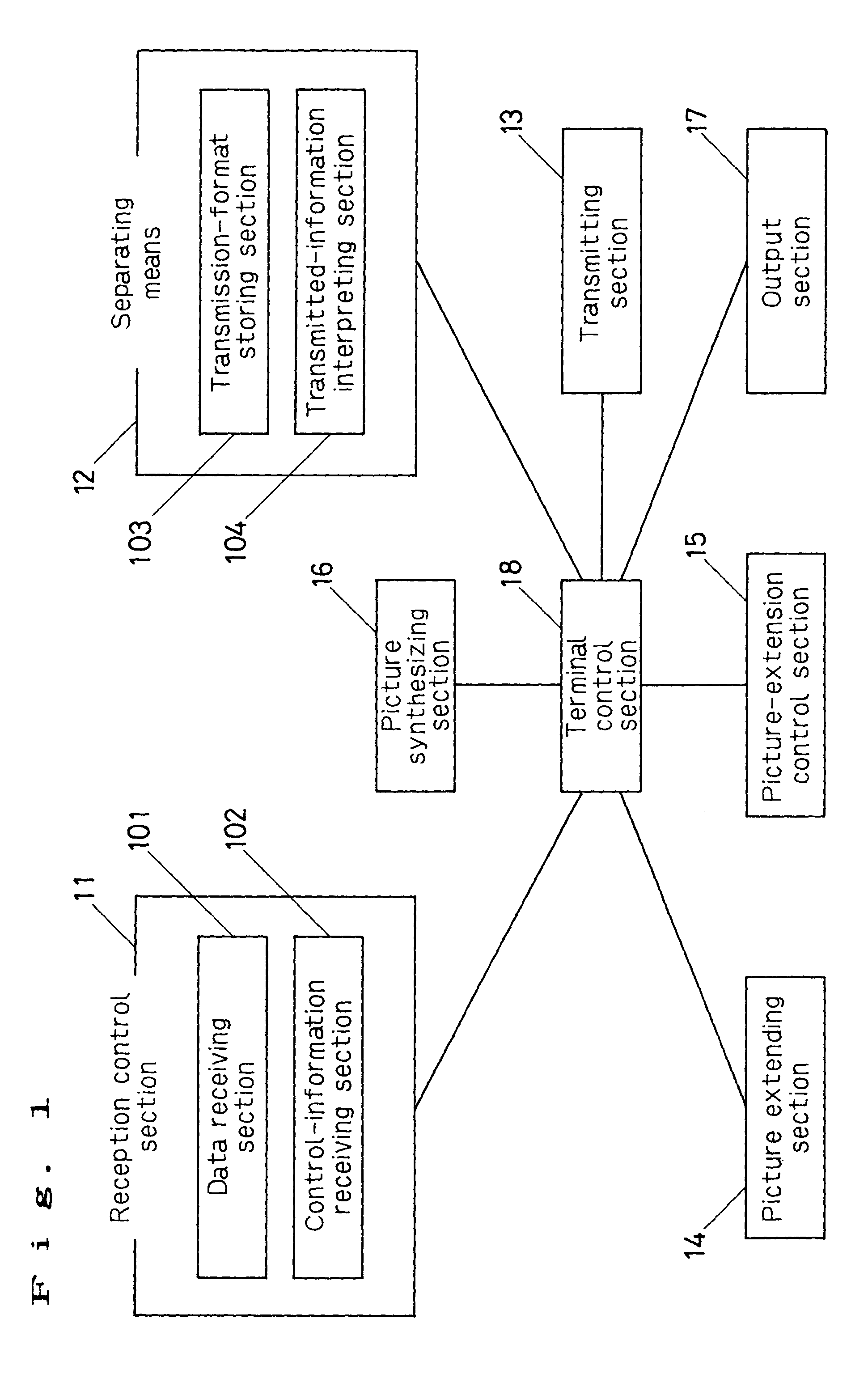
A reception control section 11 for receiving the information including data and its transmission format information from a memory or communication channel, a separating section 12 for analyzing and separating received information, a transmitting section 13 for transmitting information to a memory or transmission channel, a video extending section 14 for extending a video, and video-extension control section 15 control the processing state of said video extending section 14 for extending at least one or more videos and a video synthesizing apparatus constituted with a video synthesizing section 16 for synthesizing videos in accordance with extended information, an output section 17 for outputting a synthesized result, and a terminal control section 18 for controlling the above means makes it possible to synthesize a plurality of videos at the same time and correspond to a dynamic change of transmission format information.

Description

[0001]This application is a divisional of U.S. patent application Ser. No. 09 / 194,008, filed Mar. 17, 1999, now U.S. Pat. No. 6,674,477, which is a U.S. National Phase Application of PCT International Application PCT / JP98 / 01084.TECHNICAL FIELD[0002]The present invention relates to audio-video transmitter and audio-video receiver, data-processing apparatus and method, waveform-data-transmitting method and apparatus and waveform-data-receiving method and apparatus, and video-transmitting method and apparatus and video-receiving method and apparatus.BACKGROUND ART[0003]There has been an apparatus which satisfies the sense of real existence that a counterpart is present in front of you and aims at realistic picture communication by extracting, for example, a person's picture out of the scenery picture of a space in which you are present and superimposing the person's picture, a person's picture sent from the counterpart, and the picture of a virtual space to be displayed commonly with a...

Claims


Application Information

Patent Timeline
Patent Type & Authority Patents(United States)
IPC IPC(8): H04N7/12H04N7/26H04L1/18H04N7/14H04N7/15H04N7/24H04N7/32H04N7/36H04N7/50H04N7/52
CPCH04L1/1854H04N19/87H04N7/147H04N7/152H04N7/24H04N7/52H04N21/234327H04N21/235H04N21/236H04N21/2368H04N21/238H04N21/2381H04N21/4305H04N21/4341H04N21/435H04N21/4363H04N21/4381H04N21/44008H04N21/6137H04N21/643H04N21/6437H04N21/6543H04N21/6547H04N21/6587H04N21/84H04N21/854H04N21/85406H04N21/8547H04N19/00H04N19/50H04N19/176H04N19/46H04N19/51H04N19/102H04N19/61H04N19/132H04N19/142H04N19/156H04N19/164H04N19/18H04N19/42H04N19/523H04L1/1887H04N7/08H04N21/23
Inventor YAMAGUCHI, TAKAOETOH, MINORUARAKAWA, HIROSHI
Owner PANASONIC CORP
Learn More