Distance image sensor

a technology of distance image and sensor, which is applied in the direction of distance measurement, radiation control devices, instruments, etc., can solve the problems of low sensitivity, cost reduction, or complicated manufacturing steps

Active Publication Date: 2008-10-14
NAT UNIV CORP SHIZUOKA UNIV
View PDF7 Cites 391 Cited by
  • Summary
  • Abstract
  • Description
  • Claims
  • Application Information

AI Technical Summary

Benefits of technology

[0013]The present inventor devised that an improvement of the charge transfer efficiency and the charge storage (integration) can be implemented at a relatively low cost by adding a relatively simple step for a standard CMOS process or a CMOS image sensor, or by adding a circuit, and by this the distance image sensor with high sensitivity can be implemented. According to an embodiment of the present invention, this distance image sensor can be used in an ordinary environment since the influence of background light can be eliminated.
[0016]The principle of distributing charges to two nodes using the structure of a buried photo-diode is very close to that of prior art (3). However, prior art (3) is a CCD device, so it cannot coexist with a CMOS processing circuit. The buried photo-diode is becoming a standard technology of high image quality CMOS image sensors, and can implement a distance image sensor in a CMOS structure used for the configuration of the present patent application, using a relatively low cost and high performance CMOS image sensor technology, which is an advantage.
[0019](b) Only two charge storage nodes (or capacitors) are provided. Considering the fast reading of the image, fast speed images are further divided into two time zones. In the first time zone the modulated light is projected and the signals of the two charge storage nodes (signals which depend on the delay of the modulated light) are fetched, and in the latter time zone the modulated light is turned OFF and the signals of the two charge storage nodes generated only by the background light are fetched. The influence of the background light can be eliminated by processing these signals. However if the background changes between the two time zones, the influence of background may not be completely eliminated. Still finally the average value of the values which were read and calculated at high-speed is determined, so the influence of the background light can be decreased by this processing.

Problems solved by technology

Conventional methods for measuring the distance to an object by measuring the time of flight of the light involve either low sensitivity or have complicated manufacturing steps.
The other is transferring and storing the charges generated in a photo-diode to two capacitors alternately, synchronizing modulated light, using an amplifier, without using a special device structure (cost decreases).

Method used


Image

  • Distance image sensor
  • Distance image sensor
  • Distance image sensor

Examples


Embodiment Construction

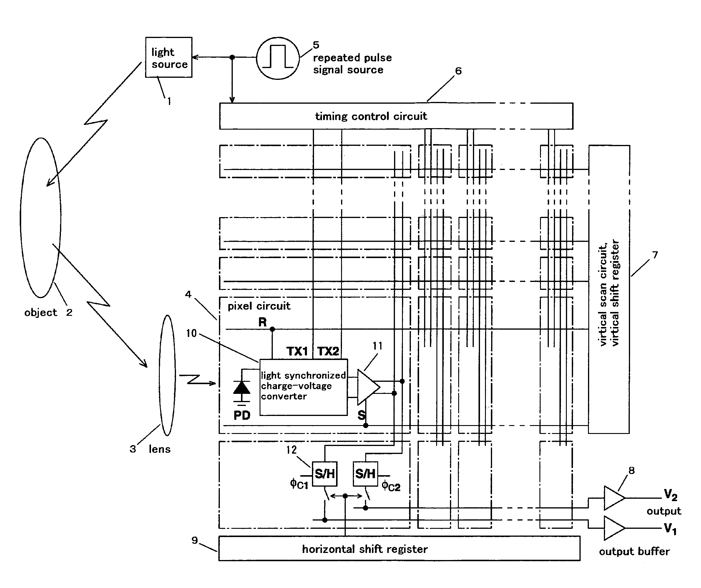
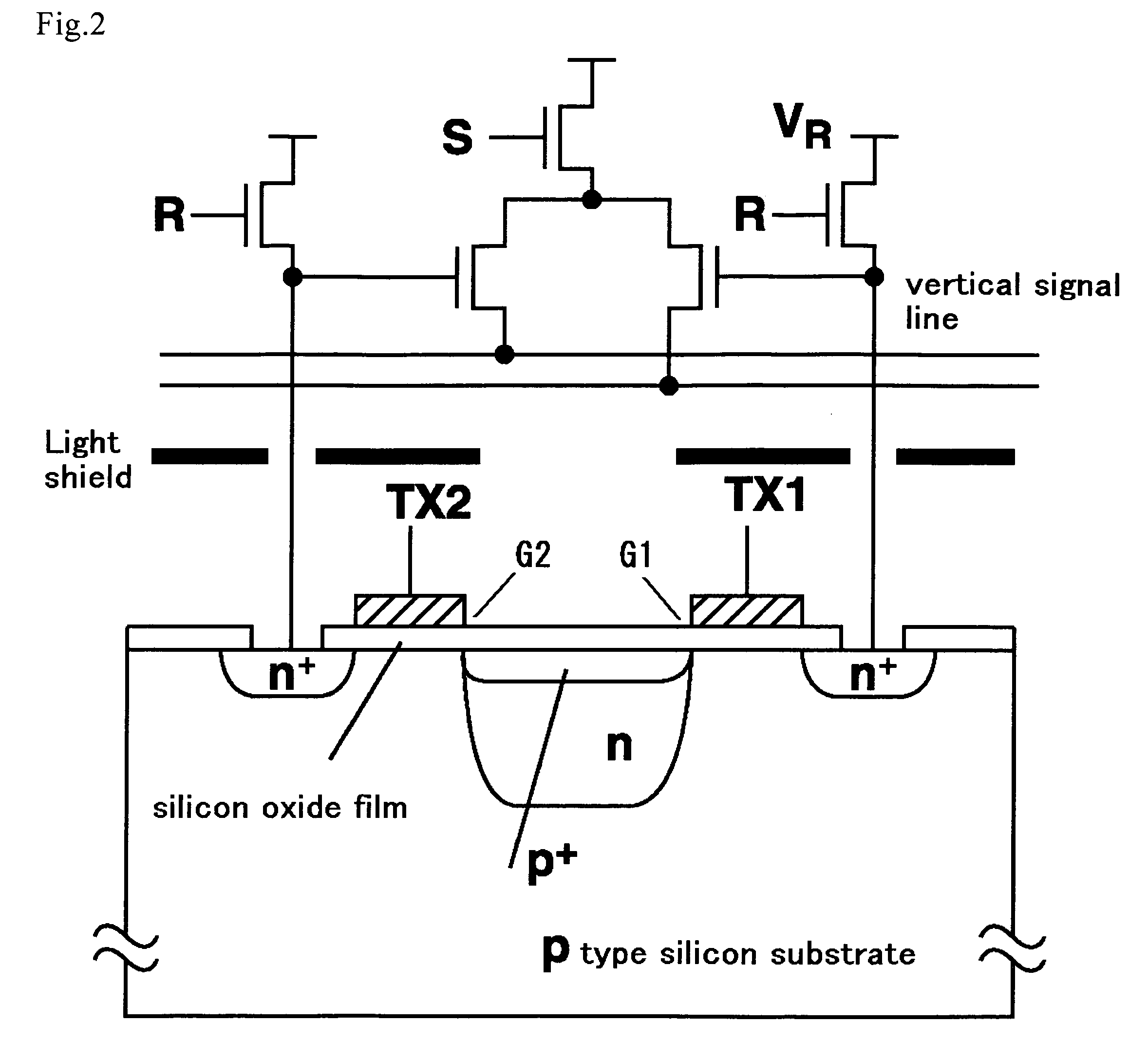
[0041]First the principle of measuring the time of flight of light while removing the background will be described using the case of the block diagram in FIG. 1 as the simplest example. This corresponds to the above mentioned principle (b). FIG. 2 is a diagram depicting the structure of each pixel, and FIG. 3 shows the equivalent circuit thereof. FIG. 4 is an operation timing chart in the circuit of each pixel. The cycle of acquiring an image at high-speed is assumed to be Th. This cycle is divided into the period Th L for projecting the pulse modulated light, and the period Th D for turning the modulated light OFF. In the period when the modulated light is projected, the light source is driven by a repeat pulse having a predetermined cycle, and emits light. This light is irradiated onto an object. The image by the reflected light thereof is formed on the distance image sensor via the lens.

[0042]Each pixel has a buried photo-diode, and the stored charges are alternately transferred ...


PUM


Abstract

A distance image sensor for removing the background light and improving the charge transfer efficiency in a device for measuring the distance to an object by measuring the time-of-flight of the light.In a distance image sensor for determining the signals of two charge storage nodes which depend on the delay time of the modulated light, a signal by the background light is received from the third charge storage node or the two charge storage nodes in a period when the modulated light does not exist, and is subtracted from the signal which depends on the delay time of the two charge storage nodes, so as to remove the influence of the background. Also by using a buried diode as a photo-detector, and using an MOS gate as gate means, the charge transfer efficiency improves. The charge transfer efficiency is also improved by using a negative feedback amplifier where a capacitor is disposed between the input and output.

Description

TECHNICAL FIELD[0001]The present invention relates to a technology for measuring the distance to an object by emitting a light to an object, receiving the light reflected from the object, and measuring the delay time, using the fact that the velocity of the light is a known.BACKGROUND ART[0002]The velocity of light is 3×10⁸ m / s. Since this is known, the distance to an object can be measured by emitting light, receiving the light reflected from the object, and measuring the delay time. The TOF (Time-Of-Flight) method is a method for measuring the distance to an object by measuring the time of the flight of the light. Table 1 shows the relationship between the resolution of the measurement of the delay time and the resolution of the distance.[0003]TABLE 1Relationship between delay time measurement resolutionand distance resolution based on the TOF methodDelay time measurement resolutionMeasurement distance resolution10μs1.5km1μs150m100ns15m10ns1.5m1ns15cm100ps1.5cm10ps1.5mm1ps0.15mm[0...

Claims


Application Information

Patent Timeline
Patent Type & Authority Patents(United States)
IPC IPC(8): G01C3/08G01C3/06G01S7/4863G01S17/894H01L27/146H01L31/101
CPCG01S7/4863H01L27/14609H01L27/14641H04N5/335H01L31/101G01S17/894H04N25/00
Inventor KAWAHITO, SHOJI
Owner NAT UNIV CORP SHIZUOKA UNIV
Why Eureka
Try Eureka