Laminated ceramic capacitor

a technology of laminated ceramic capacitors and capacitors, applied in the direction of capacitors, fixed capacitor details, fixed capacitors, etc., can solve the problems of reducing the breakdown voltage or withstand voltage, unable to achieve the desired effect in reality, and unable to crack, etc., to achieve excellent withstand voltage performance and high breakdown voltage

Active Publication Date: 2008-10-14
MURATA MFG CO LTD
View PDF13 Cites 33 Cited by
  • Summary
  • Abstract
  • Description
  • Claims
  • Application Information

AI Technical Summary

Benefits of technology

[0013]In order to overcome the problems described above, preferred embodiments of the present invention provide a laminated ceramic capacitor having a high breakdown voltage and excellent withstand-voltage performance, in which structural defects such as cracks generated during firing or structural defects caused by electrostriction (inverse piezoelectric effect) can be prevented even when a ceramic material with a high dielectric constant is used as a dielectric ceramic and even when the number of lamination layers constituted by ceramic dielectric layers and capacitance-forming inner electrode layers is increased.
[0014]According to a preferred embodiment of the present invention, a laminated ceramic capacitor includes at least two capacitance forming layers in which at least one ceramic dielectric layer and capacitance-forming inner electrode layers that contribute to the formation of electrostatic capacitance are laminated; at least one stress relieving layer in which ceramic dielectric layers and at least one dummy inner electrode layer that does not contribute to the formation of electrostatic capacitance are laminated, the stress relieving layer being disposed between two adjacent capacitance forming layers so as to relieve stress caused by electrostriction in the capacitance forming layers; and capacitance-formation-preventing inner electrode layers that prevent capacitance from being formed between the capacitance-forming inner electrode layers and the dummy inner electrode layer, each of the capacitance-formation-preventing inner electrode layers being disposed between each of the capacitance forming layers and the stress relieving layer.

Problems solved by technology

This leads to crack generation and a reduction in breakdown voltage or withstand voltage.
However, the structure and the arrangement of the inner electrode layers need to be appropriately adjusted so as to effectively relieve the contraction difference generated between the capacitance forming layers and the intermediate layer, and desired effects are not easily produced in reality.

Method used


Image

  • Laminated ceramic capacitor
  • Laminated ceramic capacitor
  • Laminated ceramic capacitor

Examples


Embodiment Construction

[0039]Features of the present invention will now be described in detail with reference to preferred embodiments thereof.

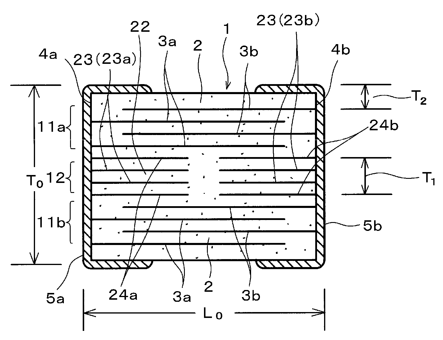
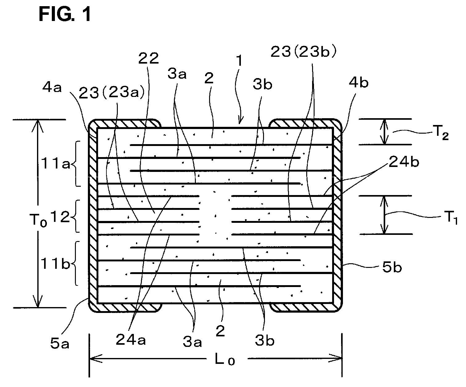
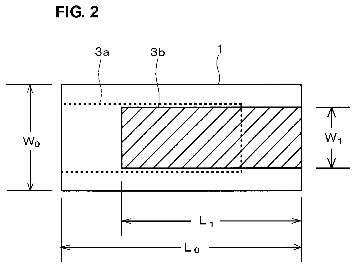
[0040]FIG. 1 is a cross-sectional view schematically illustrating the structure of a laminated ceramic capacitor according to a preferred embodiment of the present invention. FIG. 2 is a plan view illustrating capacitance-forming inner electrode layers disposed in capacitance forming layers of the laminated ceramic capacitor shown in FIG. 1. FIG. 3 is a plan view illustrating dummy inner electrode layers disposed in a stress relieving layer (intermediate layer) of the laminated ceramic capacitor shown in FIG. 1.

[0041]As shown in FIG. 1, a laminate (ceramic element) 1 constituting the laminated ceramic capacitor according to the first preferred embodiment includes a pair of capacitance forming layers 11a and 11b and a stress relieving layer (intermediate layer) 12 disposed between the pair of capacitance forming layers 11a and 11b. Each of the capacitance forming la...


PUM

PropertyMeasurementUnit
thicknessaaaaaaaaaa
thicknessaaaaaaaaaa
thicknessaaaaaaaaaa

Abstract

A laminated ceramic capacitor has a high breakdown voltage and excellent withstand-voltage performance, and prevents cracks generated during firing even when the number of lamination layers constituted by ceramic layers and inner electrode layers is increased. The laminated ceramic capacitor includes capacitance forming layers in which ceramic dielectric layers and capacitance-forming inner electrode layers are laminated, and a stress relieving layer. The stress relieving layer is disposed between the capacitance forming layers. In the stress relieving layer, ceramic dielectric layers, dummy inner electrode layers (split electrodes) that do not contribute to the formation of electrostatic capacitance, and capacitance-formation-preventing inner electrode layers that prevent capacitance from being formed between the capacitance-forming inner electrode layers and the dummy inner electrode layers are laminated. The thickness of the stress relieving layer is in the range of about 100 μm to about 300 μm inclusive. The plane area of the dummy inner electrode layers is about 60% or more of that of the capacitance-forming inner electrode layers. The dummy inner electrode layers are undivided or are divided into two or three parts in a single layer. With this structure, stress caused by electrostriction is relieved.

Description

BACKGROUND OF THE INVENTION[0001]1. Field of the Invention[0002]The present invention relates to laminated ceramic capacitors, and in particular, relates to technologies of laminated ceramic capacitors of which structural defects such as cracks generated during firing while the laminated ceramic capacitors are produced or structural defects caused by electrostriction (inverse piezoelectric effect) can be controlled or prevented.[0003]2. Description of the Related Art[0004]As shown in FIG. 11, a typical laminated ceramic capacitor includes a plurality of inner electrode layers 53a and 53b that oppose each other with ceramic layers (dielectric layers) 52 disposed therebetween and a pair of outer electrodes 55a and 55b disposed at end surfaces 54a and 54b, respectively, of a ceramic element 51. Ends of the inner electrode layers 53a and 53b are alternately extended to the corresponding end surfaces so as to be electrically connected to the outer electrodes 55a and 55b, respectively.[00...

Claims


Application Information

Patent Timeline
Patent Type & Authority Patents(United States)
IPC IPC(8): H01G4/06
CPCH01G4/012H01G4/30
Inventor OGUNI, TOSHIMIMATSUMOTO, HIROYUKI
Owner MURATA MFG CO LTD
Why Eureka
Try Eureka