
Shaped high frequency vibratory source

a high-frequency, vibratory source technology, applied in the field of seismic data acquisition and processing of seismic source data, can solve the problems of no longer causal data, no well-defined arrival time, and undesirable pulse characteristics, and achieve the effect of improving noise suppression

Active Publication Date: 2008-10-14
EXXONMOBIL UPSTREAM RES CO
View PDF35 Cites 60 Cited by
  • Summary
  • Abstract
  • Description
  • Claims
  • Application Information

AI Technical Summary

Benefits of technology

[0013]The present invention is a method of processing seismic data in which one or more seismic vibrators are activated with one or more pilot signals and vibrator motions are recorded along with seismic data. Vibrator signatures are computed from measured vibrator motions, such as the ground force signal. A desired impulse response is specified from either a measured vibrator motion or from test data or field data from a location near the location from which the seismic data was acquired. A deconvolution filter is computed from the impulse response and the vibrator signature. Alternatively, a single separation and deconvolution filter is derived from the impulse response and from vibrator signatures from multiple vibrators and sweeps. The deconvolution or deconvolution and separation filter is used to process the seismic data. The vibrators are then moved to a new location, and the activation is repeated. The impulse response is determined based on an iterative process in which time and frequency domain characteristics of it and a sample filter are analyzed. After application of a separation and deconvolution filter, data are obtained that are suitable for correcting intra-array effects and for improved noise suppression.

Problems solved by technology

First, the cross-correlation process results in a pulse with undesirable characteristics, including a widened main lobe and sidelobes that appear as oscillations on either side of the main lobe.
This leads to several problems.
For example, correlated data, unlike impulsive-source data, do not have well-defined arrival times. In addition, such data are no longer causal.
Other processing techniques, such as statistical or spiking deconvolution, assume that the data are causal and minimum phase, and for that reason the processing results may not be accurate.
Third, the pilot signal used in the correlation is generally substantially different from the actual signal put into the ground.
Processing the data with the pilot signal does not allow those harmonics and nonlinearities to be removed, which therefore appear as noise in the processed data.
Fourth, acquiring seismic data is expensive and a major cost is associated with the number of source stations that can be used.
However, spacing limitations result in the multiple vibrators forming an array that can limit the high frequencies in the data and thereby reduce resolution.
Elevation changes may also limit the ability to correct for time shifts, also referred to as static corrections, between the vibrators.
However, processing is done with the pilot, which is only an approximation of the signature imparted into the ground.
This step prevents numerical errors in the division, but also may cause phase distortions and adds a precursor to the processed seismic data.
This solution, however, only addresses the first of the problems noted above.
In addition, the use of high-resolution wavelets requires that the sweep rate changes rapidly with time and is not realizable with standard hydraulic vibrators.
However, Allen's method applies an inverse filter by the process of spectral division, and it is recognized that a problem with such inverse filters is that at frequencies where the measured signals are small, the filter will apply a large gain and amplify any recorded noise.
If the signal is zero, then inversion will be unstable.
The data can be pre-whitened by adding a small amount of constant noise to stabilize the inversion, but the added noise can distort the phase of the data.
Because processing techniques such as spiking deconvolution assumes that input data are minimum phase, the output results may not be predictable when such distortion is present.
Although Sallas addresses the shortcomings listed above, the problems with inversion and phase errors discussed above in relation to Allen remain unsolved.
This approach also involves retention of noise components that reduce the quality of the subsequently processed data.
As noted, filters are undesirable, as they inadequately remove harmonics and other non-linearities and thus reduce the quality of subsequently processed data.

Method used


Image

  • Shaped high frequency vibratory source
  • Shaped high frequency vibratory source
  • Shaped high frequency vibratory source

Examples


third embodiment

[0037]In a third embodiment, the method of the present invention facilitates processing to be applied for separating the data from each vibrator into individual records. Static corrections and differential normal moveout (NMO) can then be applied to each source location. In addition, supergathers can be constructed which improve the capabilities of noise separation techniques. The data from each source location can be summed. Alternatively, data can be binned at smaller common depth point intervals prior to migration, thereby further improve imaging and focusing.

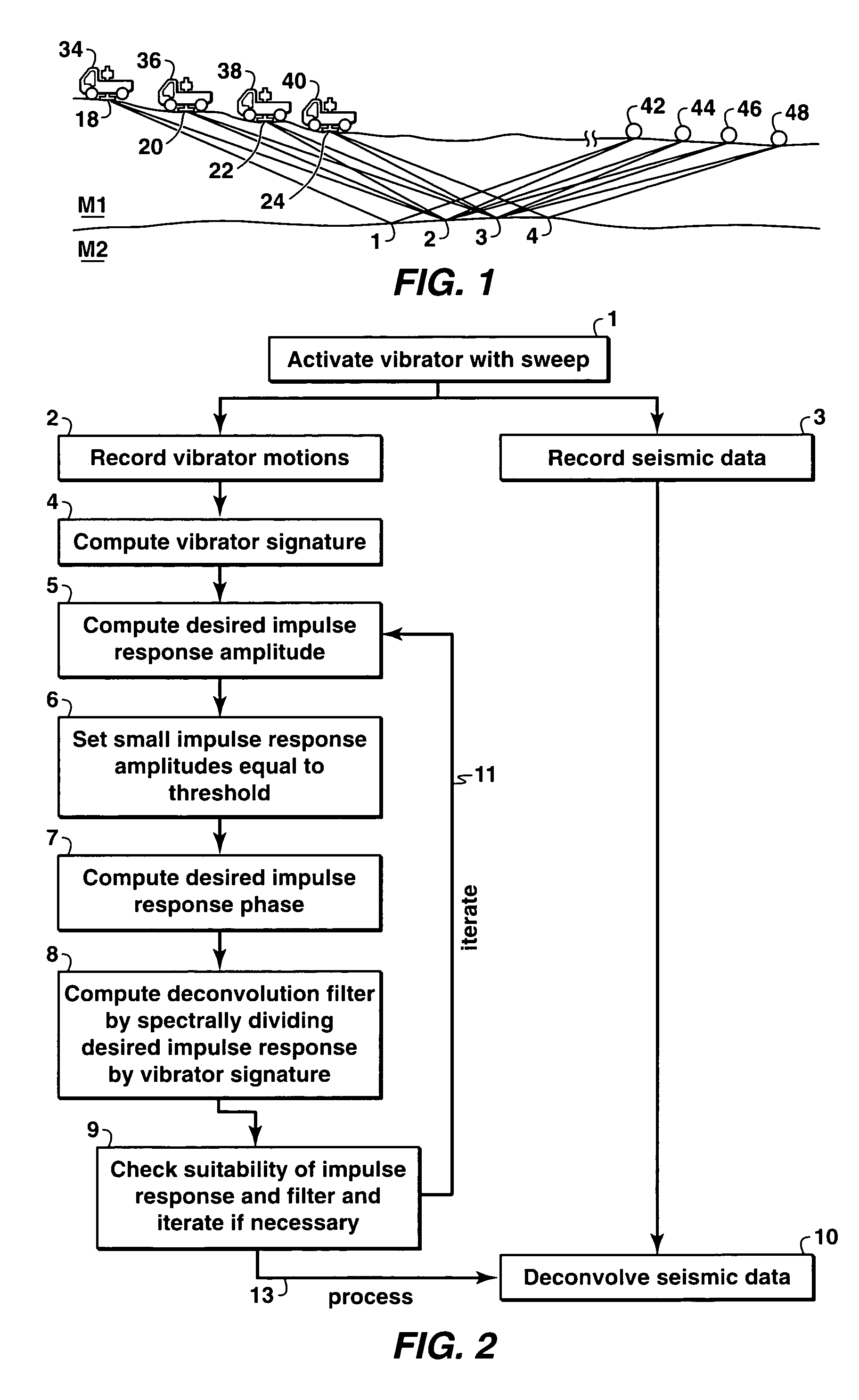
[0038]Embodiments of the present invention will be discussed in the following in association with the system diagram of FIG. 1, which depicts the geometry of the data gathering system associated with the present invention. In FIG. 1, vibrators 18, 20, 22, and 24 are located, in an on-land application, on trucks 34, 36, 38, and 40, respectively. Signals that are generated in the earth by vibrators 18, 20, 22, and 24 are refle...

first embodiment

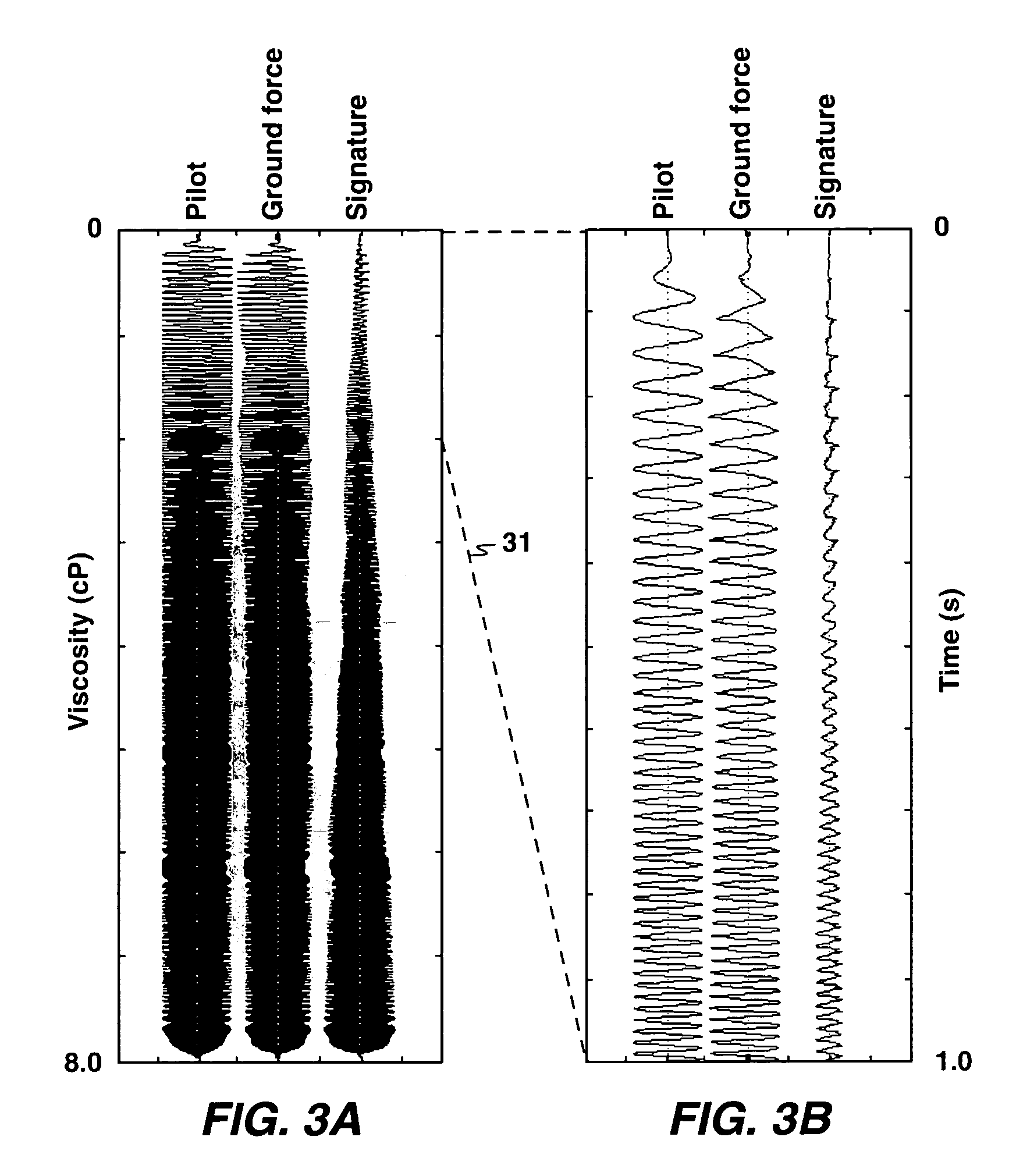
[0039]the method of the present invention, as depicted in the flow chart of FIG. 2, begins with the activation of one or more vibrators with a sweep, step 1. Next, vibrator motions, step 2 and seismic data, step 3 are both recorded. Third, a vibrator signature is computed from the measured vibrator motions, step 4. Next, a desired impulse response is computed. This involves the specification of a desired impulse response amplitude spectrum, step 5 which is preferably less than or equal to the vibrator signature spectrum at all frequencies. Preferably, the amplitudes of the impulse response and the vibrator signature that fall below a small threshold value are set equal to the threshold value, step 6. Alternatively, a small amount of prewhitening noise can be added at all frequencies (Not depicted in FIG. 1). Next, a desired phase for the impulse response is calculated, step 7. A deconvolution filter is computed by spectrally dividing the calculated impulse response by the vibrator s...

second embodiment

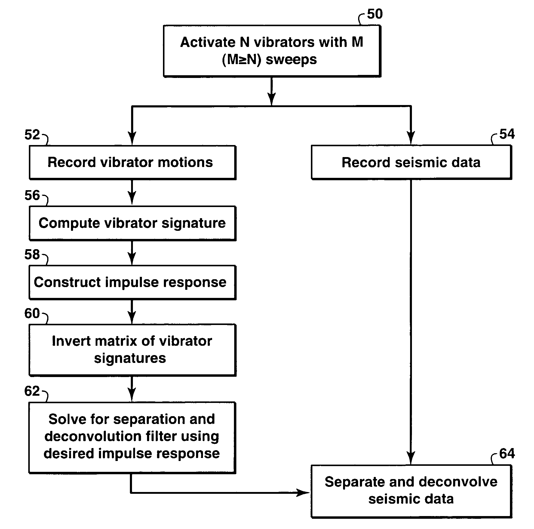
[0058]In the present invention, a vibrator signature deconvolution is performed within a matrix separation scheme for a number of vibrators operated simultaneously. In this embodiment, a plurality of vibrators is then employed to perform a number of sweeps. The number of sweeps should be equal to or greater than the number of vibrators. Measurements are made of both the motions of the vibrators and the received seismic signals. Next, vibrator signatures are computed, with the amplitudes clipped at a minimum threshold value. A desired impulse response is constructed next, as described above. A deconvolution matrix operator is generated in the frequency domain that separates the earth response for each vibrator and replaces the individual vibrator signatures with the desired impulse response. That operator is applied to deconvolve the seismic data and to separate that data according to the individual vibrator locations.

[0059]In this second embodiment, multiple sweeps, in a number equa...


PUM


Abstract

The present invention is a method of processing seismic data in which one or more seismic vibrators are activated with one or more pilot signals and vibrator motions are recorded along with seismic data. Vibrator signatures are computed from measured vibrator motions, such as the ground force signal. A desired impulse response is specified from either a measured vibrator motion or from test data or field data from a location near the location from which the seismic data was acquired. A deconvolution filter is computed from the impulse response and the vibrator signature. Alternatively, a single separation and deconvolution filter is derived from the impulse response and from vibrator signatures from multiple vibrators and sweeps. The deconvolution or deconvolution and separation filter is used to process the seismic data. The vibrators are then moved to a new location, and the activation is repeated.

Description

FIELD OF THE INVENTION[0001]This invention relates to the field of seismic data acquisition and processing of vibratory source data. Specifically, this invention is a method of optimizing vibratory source data to accurately represent the output that would be derived from impulse sources.BACKGROUND OF THE INVENTION[0002]Seismic vibrators are commonly used to produce the source signals necessary in the geophysical exploration for hydrocarbons. In field use, seismic vibrators are excited with a pilot signal that is typically a wave train that varies in frequency, referred to as a sweep, and lasts several seconds. The excitation of the vibrator is typically adjusted by a feedback loop controlled by a ground force signal that is computed from signals measured by accelerometers on the base plate and on the reaction mass of the source.[0003]In this application of seismic vibrators, seismograms are generated by cross correlating the data recorded at various receiver locations with the pilot...

Claims


Application Information

Patent Timeline
Patent Type & Authority Patents(United States)
IPC IPC(8): G01V1/00G01V1/155G01VG01V1/36
CPCG01V1/005G01V1/368G01V1/37
Inventor KROHN, CHRISTINE E.
Owner EXXONMOBIL UPSTREAM RES CO
Learn More