
Image processing apparatus and method

a technology of image processing and apparatus, applied in the field of image processing apparatus and method, can solve the problems of subjective image quality seriously degraded, remarkable block distortion and/or mosquito noise in an area, and the effect of high image quality and simple processing

Inactive Publication Date: 2008-10-14
CANON KK
View PDF3 Cites 8 Cited by
  • Summary
  • Abstract
  • Description
  • Claims
  • Application Information

AI Technical Summary

Benefits of technology

[0009]The present invention has been made in consideration of the above-described problems, and has its object to realize high-performance image quantization maintaining high image quality by simple processing.
[0010]Further, another object of the present invention is to realize high-performance image data compression maintaining high image quality by changing a quantization characteristic in a specific area extracted from an image and other areas.
[0012]Further, another object of the present invention is to attain high-speed specific-area extraction processing by extracting the specific area using a low-frequency component image data resulted from wavelet conversion processing.
[0013]Further, another object of the present invention is to attain high-speed specific-area extraction processing by using image data thinned in accordance with a predetermined reduction rate to extract the specific area.

Problems solved by technology

However, in application to a narrow-bandwidth communication environment such as the Internet, as the coding amount must be greatly reduced with a high compression rate, a problem occurs due to degradation of image quality even in use of these high-performance compression coding methods.
However, in case of coding amount control based on each image area by using the conventional DCT-based coding method, remarkable block distortion and / or mosquito noise occurs in an area determined as a part other than an important part.
Accordingly, the subjective image quality is seriously degraded, and a decoded image seems unnatural.
Further, a pseudo outline occurs in the border between an area determined as an important part and an area determined as a part other than the important part, and the obtained image seems further unnatural.

Method used


Image

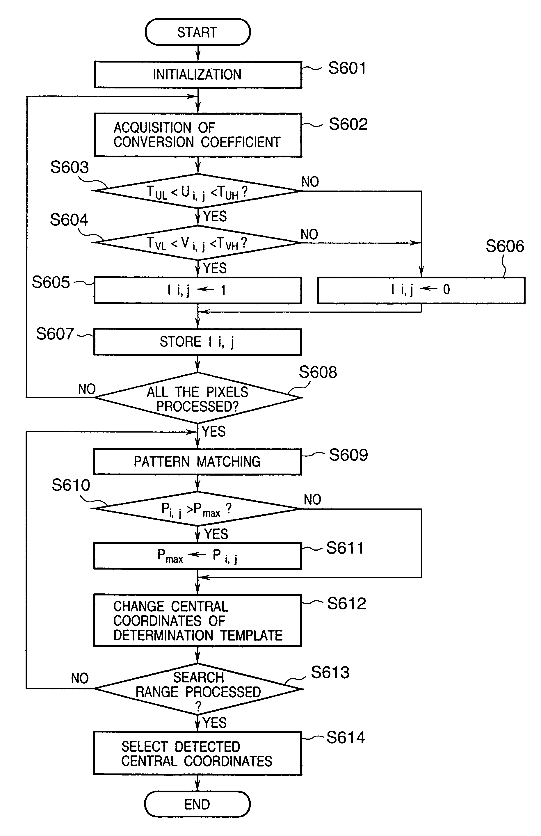
  • Image processing apparatus and method
  • Image processing apparatus and method
  • Image processing apparatus and method

Examples


Embodiment Construction

[0032]A preferred embodiment of the present invention will now be described in detail in accordance with the accompanying drawings.

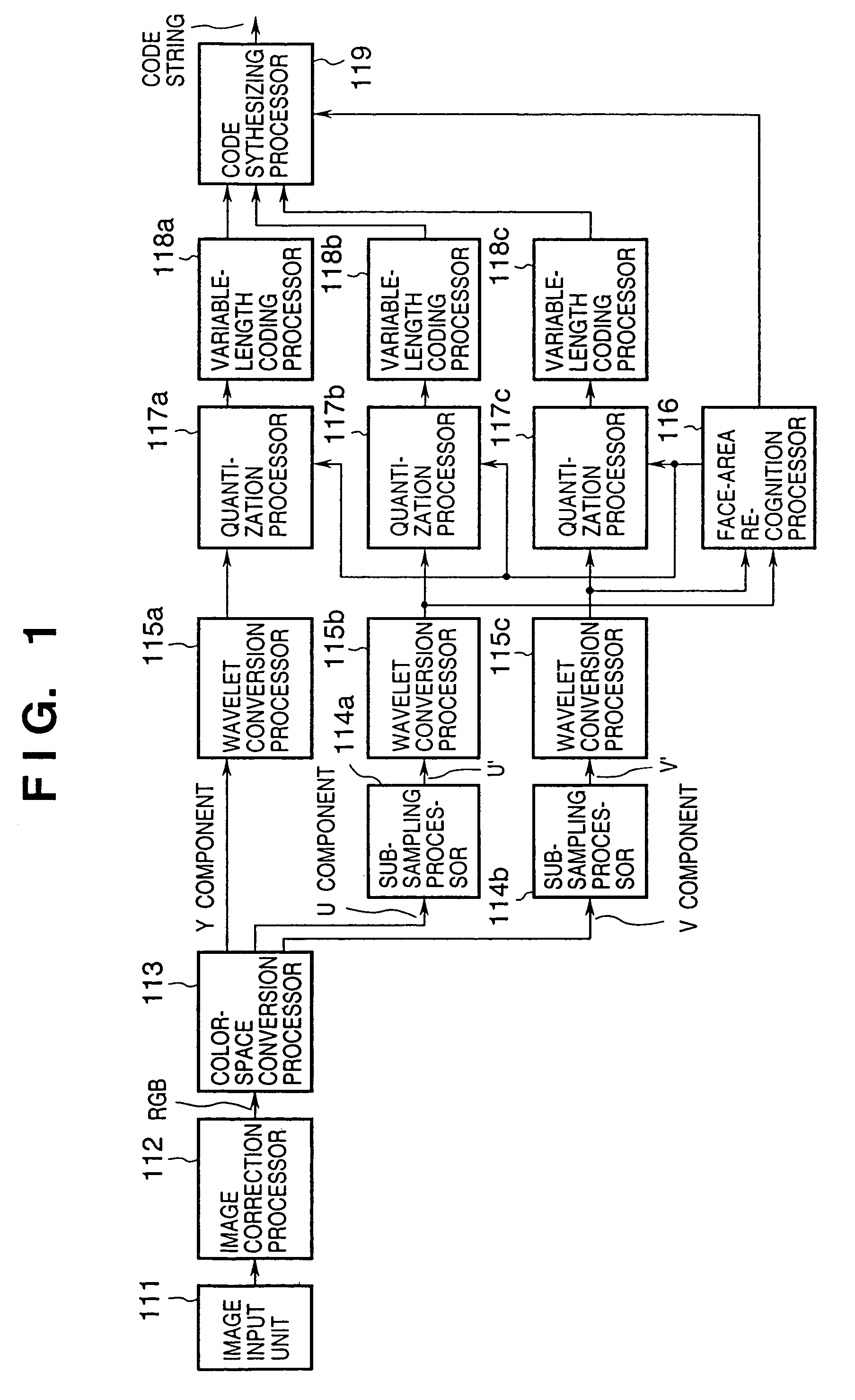
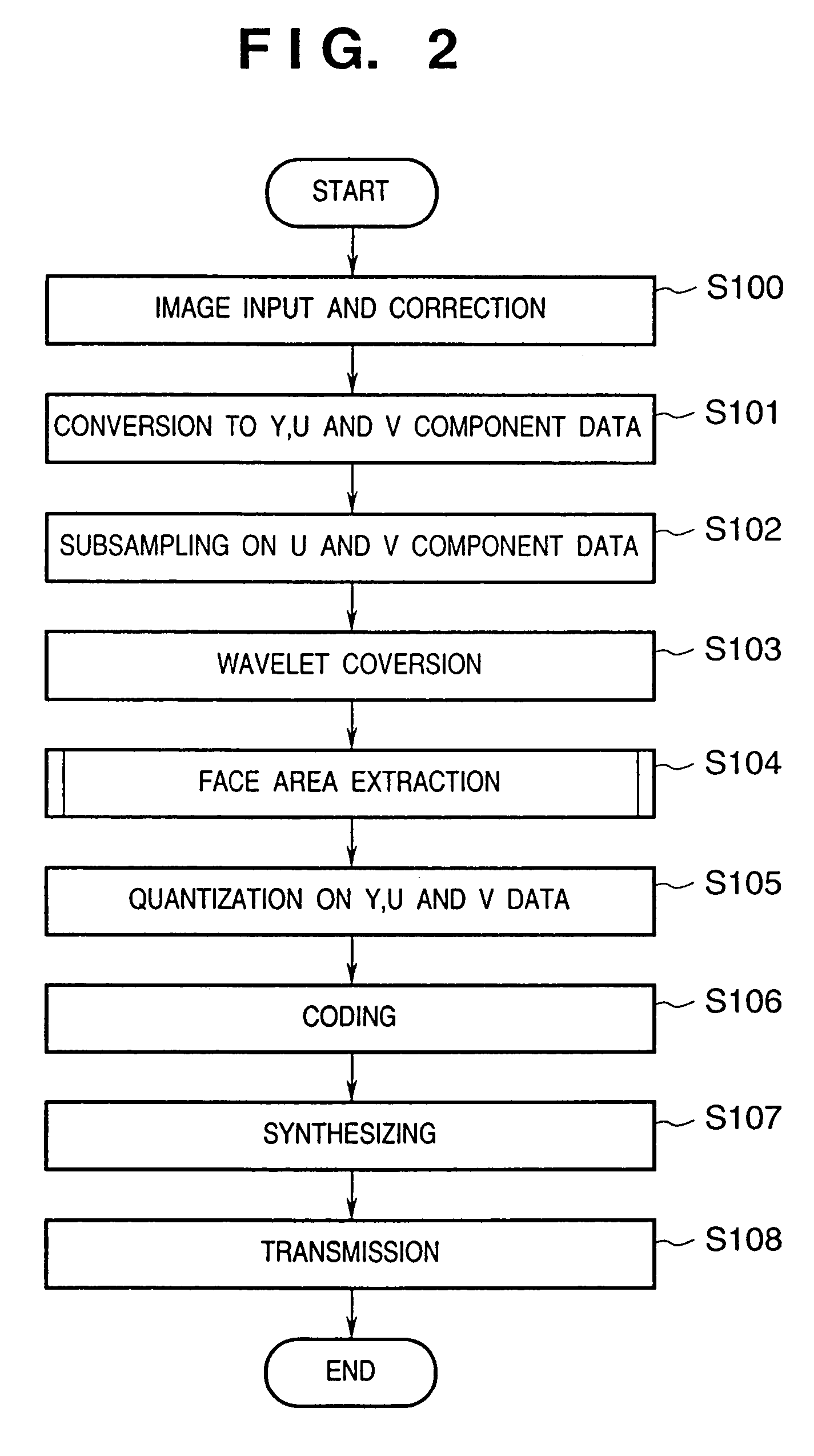
[0033]FIG. 1 is a block diagram showing the construction for image coding processing according to the embodiment of the present invention. FIG. 2 is a flowchart showing the flow of the image coding processing according to the embodiment.

[0034]In FIG. 1, reference numeral 111 denotes an image input unit which A / D converts an analog video signal obtained by a image sensing device, and outputs the converted signal as a digital image signal; 112, an image correction processor which performs desired processing of various correction processings such as image-size format generation, noise removal and resolution correction (step S100 in FIG. 2); and 113, a color-space conversion processor which performs color-space conversion processing on RGB digital image data as outputs from the image correction processor 112, to generate luminance and color difference signal...


PUM


Abstract

A color-space conversion processor converts input digital image data into YUV color space, and a wavelet conversion processor performs wavelet conversion processing on the data. A face-area recognition processor extracts a face area in the image based on the obtained conversion coefficients. A quantization processor performs quantization processing on the input conversion coefficients while changing quantization coefficients used in the quantization processing in and out of the extracted face area. A variable-length coding processor encodes the quantized coefficients. A code synthesizing processor synthesizes the obtained respective color component code data with information indicating the face area extracted by the face-area recognition processor, and outputs the synthesized data as a code string.

Description

[0001]This application is a division of Application No. 09 / 466,907, filed Dec. 20, 1999 now U.S. Pat. No 6,665,446.BACKGROUND OF THE INVENTION[0002]The present invention relates to an image processing apparatus and method preferably applicable to a video communication apparatus in a video conference system or the like using video and audio data.[0003]As image compression methods used in video communication apparatuses, high-performance coding methods based on DCT (Discrete Cosine Transformation) as in the ITU-T Recommendations H.261, H263 and the like are widely used. However, in application to a narrow-bandwidth communication environment such as the Internet, as the coding amount must be greatly reduced with a high compression rate, a problem occurs due to degradation of image quality even in use of these high-performance compression coding methods.[0004]Accordingly, in a video conference system or the like, a method for satisfying subjective image quality has been developed. That ...

Claims


Application Information

Patent Timeline
Patent Type & Authority Patents(United States)
IPC IPC(8): G06K9/36G06K9/38H04N11/04H04N5/21H04N7/12H04N11/02H04N19/102H04N19/11H04N19/126H04N19/136H04N19/167H04N19/169H04N19/172H04N19/186H04N19/189H04N19/196H04N19/33H04N19/37H04N19/59H04N19/60H04N19/63H04N19/86H04N19/91
CPCG06T9/001H04N19/63H04N19/40H04N19/17H04N19/124
Inventor KATO, MASAMI
Owner CANON KK
Learn More