Device for use in placer mining operations and method

a placer and mining technology, applied in the field of placer mining machinery, can solve the problems of not being able to separate and recover very fine mineral particles, such as black sand and gold flour, from mineral bearing placer ore, and having to wash away the extremely fine particulates of heavier minerals with the discarded aggregate material

Inactive Publication Date: 2008-10-21
STOLWORTHY WADE
View PDF26 Cites 13 Cited by
  • Summary
  • Abstract
  • Description
  • Claims
  • Application Information

AI Technical Summary

Benefits of technology

[0009]The invention provides an aggregate material separating device including a frame with a shaker mechanism. A trough is disposed on the frame and coupled to the shaker mechanism by a shaker spring. A loading hopper is disposed at an upstream end of the trough and can receive a load of aggregate material. A water supply irrigates the aggregate material in the hopper forming a slurry. A brush is disposed in the trough above the mineral separation bed to slow slurry movement from the trough to the mineral separation bed in order to provide additional settling time for the slurry. A backwash spigot can be disposed in the trough above the mineral separation bed to spray a continuous flow of water toward the brush in order to create a standing wave. The standing wave can drive the slurry away from the mineral separation bed at an angle in order to provide for additional settling time for the slurry. A mineral separation bed is disposed along a bottom and side of the trough.

Problems solved by technology

Recovery of the small volume of minerals from such placer ore has had little if any commercial value because of the large recovery cost in manpower, equipment time, etc. as compared to the value of the minerals.
One problem with sluice separators is that they are unable to separate and recover very fine mineral particles, such as black sand and gold flour, from mineral bearing placer ore.
These devices have had problems keeping the extremely fine particulates of the heavier minerals from being washed away with the discarded aggregate material.

Method used


Image

  • Device for use in placer mining operations and method
  • Device for use in placer mining operations and method
  • Device for use in placer mining operations and method

Examples


Embodiment Construction

[0018]Reference will now be made to the exemplary embodiments illustrated in the drawings, and specific language will be used herein to describe the same. It will nevertheless be understood that no limitation of the scope of the invention is thereby intended. Alterations and further modifications of the inventive features illustrated herein, and additional applications of the principles of the inventions as illustrated herein, which would occur to one skilled in the relevant art and having possession of this disclosure, are to be considered within the scope of the invention.

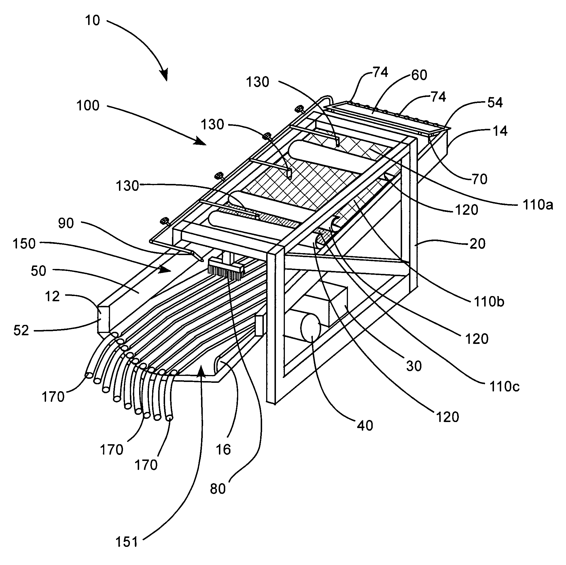
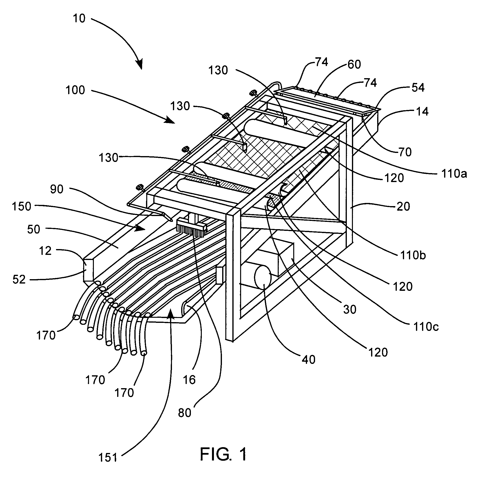
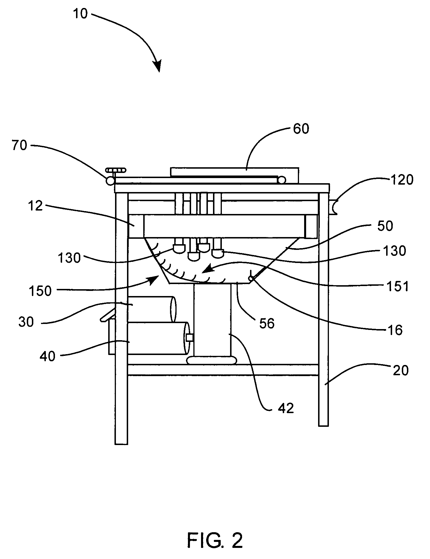
[0019]The present invention generally provides for an aggregate material separating device for use in placer mining and / or the separation of any aggregate material by elutriation and processes involving differentiation by means of specific gravity, such as shaking or vibration. The machine is operated by loading the aggregate material to be separated into a loading hopper. Once in the hopper, the aggregate materi...


PUM


Abstract

An aggregate material separating device includes a frame with a shaker mechanism. A trough is disposed on the frame and coupled to the shaker mechanism by a shaker spring. A hopper is disposed at an end of the trough and can receive a load of aggregate material. A hopper wash line is disposed adjacent the loading hopper to irrigate the aggregate material in the hopper forming a slurry. A brush and a backwash spigot form a standing wave in the trough to slow slurry movement from through the trough in order to provide additional settling time for the slurry. A mineral separation bed is disposed along a bottom and side of the trough. The mineral separation bed has a plurality of substantially longitudinal riffles that can be sized, shaped and oriented to capture minerals of a predetermined specific gravity from the slurry as the shaker shakes the trough.

Description

PRIORITY CLAIM[0001]This application claims benefit of U.S. Provisional Application No. 60 / 760,996, filed Jan. 20, 2006, which is herein incorporated by reference in its entirety for all purposes.BACKGROUND OF THE INVENTION[0002]1. Field of the Invention[0003]The present invention relates generally to placer mining machinery, and more particularly to devices for separating heavy minerals from aggregate material.[0004]2. Related Art[0005]Small volumes of valuable minerals may be present in naturally occurring aggregate materials, and also in processed ore, or tailings, from mining processes such as dredging, dry washing, sluicing, and trammeling. Recovery of the small volume of minerals from such placer ore has had little if any commercial value because of the large recovery cost in manpower, equipment time, etc. as compared to the value of the minerals. Various types of devices have been developed to try to recover precious metals, minerals and gemstones from these natural or proces...

Claims


Application Information

Patent Timeline
Patent Type & Authority Patents(United States)
IPC IPC(8): B07B1/00
CPCB03B5/04B07B13/003
Inventor STOLWORTHY, WADE
Owner STOLWORTHY WADE
Why Eureka
Try Eureka