Fuel cell

a fuel cell and cell technology, applied in the field of fuel cells, can solve the problems of inefficiency in power generation, and achieve the effect of suppressing tightening load and simple and compact structur

Inactive Publication Date: 2008-10-28
HONDA MOTOR CO LTD
View PDF17 Cites 3 Cited by
  • Summary
  • Abstract
  • Description
  • Claims
  • Application Information

AI Technical Summary

Benefits of technology

[0008]A general object of the present invention is to provide a fuel cell having a simple and compact structure, in which it is possible to suppress the tightening load locally applied to an electrolyte electrode assembly of the fuel cell.
[0009]A main object of the present invention is to provide a fuel cell in which the efficient current collection is achieved.
[0014]It is preferable that the mountain shaped protrusion is disposed in a recess formed by the annular protrusion. With this structure, the tightening load is efficiently transmitted to the electrolyte electrode assembly. Further, since the volume of the gas flow field is not decreased excessively, the pressure loss is not increased excessively, and the desired power generation reaction is induced.
[0017]According to the present invention, the first and second protrusions are provided on a single plate. Therefore, the distance between the first and second protrusions as current collectors is small, and the load in the stacking direction is transmitted efficiently. Further, the dimensional variation of the height does not affect the dimension in the stacking direction since the variation is absorbed by the first and second protrusions. Therefore, variation of the load applied to the electrolyte electrode assembly is prevented. Further, in the presence of the first and second protrusions, the electrolyte electrode assembly tightly contacts the separators for achieving the desired current collection. Therefore, the current loss between the electrolyte electrode assembly and the separators is reduced, and improvement in the current collection efficiency is achieved.
[0018]Further, the shape of the first protrusion is different from the shape of the second protrusion. Thus, the volume of the first space and the volume of the second space can be determined separately. Therefore, it is possible to sufficiently supply the desired amount of the reactant gases to the first and second spaces for inducing the desired power generation reactions. Improvement in the current collection efficiency is achieved.

Problems solved by technology

Consequently, damage or the like may occur in the electrolyte electrode assembly 9 undesirably, and the power generation cannot be carried out efficiently.

Method used


Image

  • Fuel cell
  • Fuel cell
  • Fuel cell

Examples


first embodiment

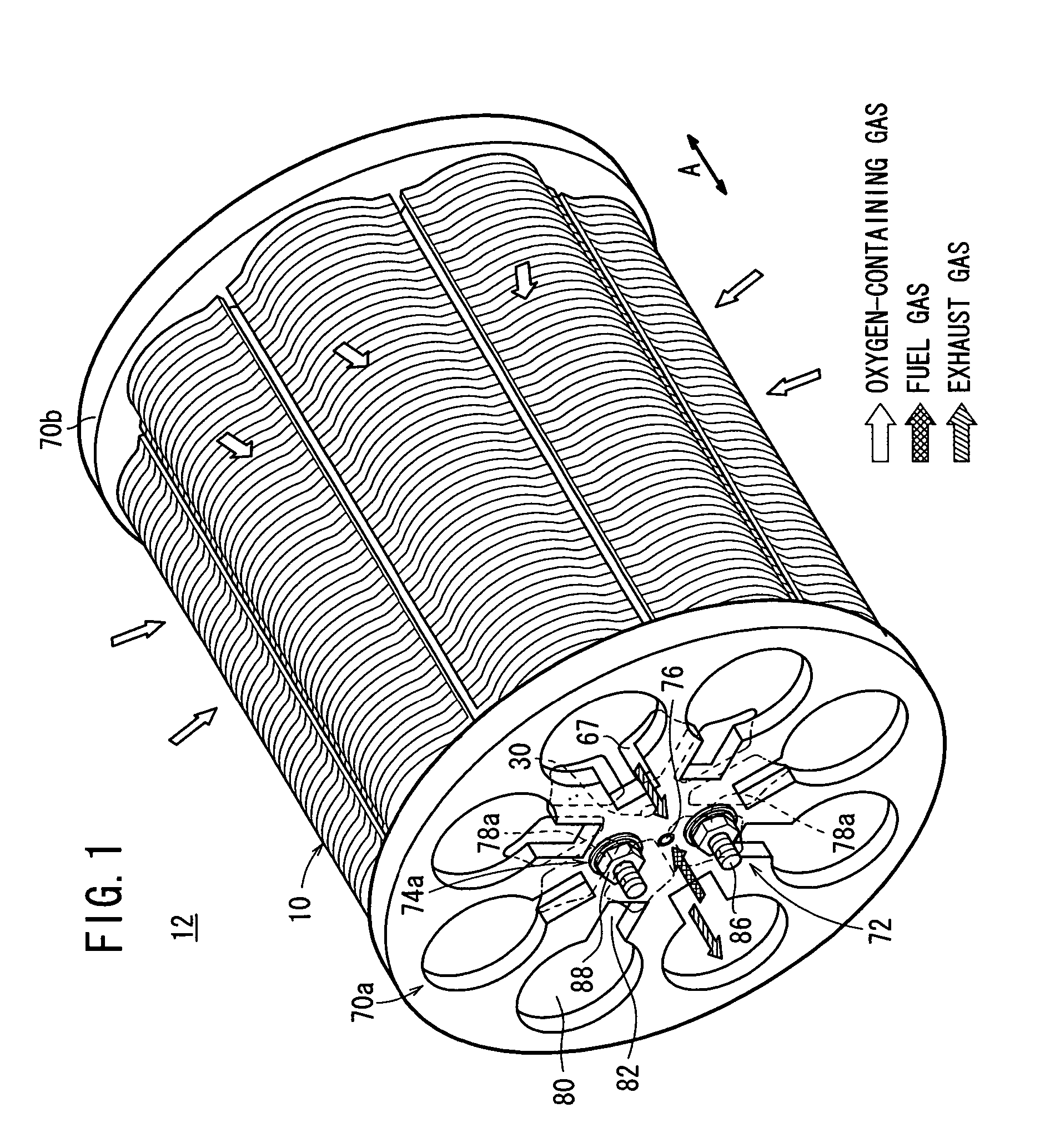
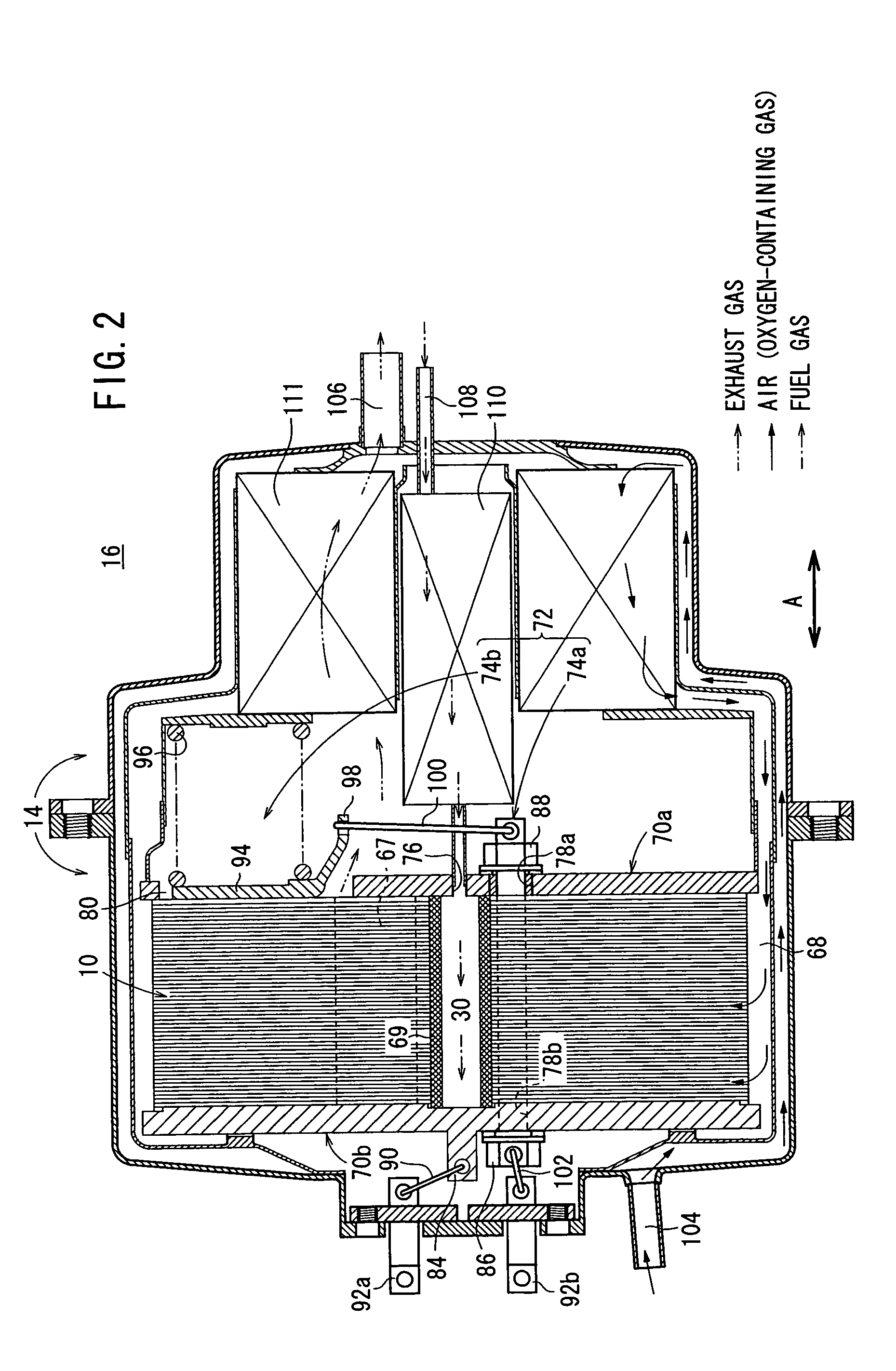
[0037]FIG. 1 is a perspective view schematically showing a fuel cell stack 12 formed by stacking a plurality of fuel cells 10 according to the present invention indicated by an arrow A. FIG. 2 is a cross sectional view showing part of a fuel cell system 16 in which the fuel cell stack 12 is disposed in a casing 14.

[0038]The fuel cell 10 is a solid oxide fuel cell (SOFC) used in various applications, including stationary and mobile applications. As shown in FIGS. 3 and 4, the fuel cell 10 includes electrolyte electrode assemblies 26. Each of the electrolyte electrode assemblies 26 includes a cathode 22, an anode 24, and an electrolyte (electrolyte plate) 20 interposed between the cathode 22 and the anode 24. For example, the electrolyte 20 is made of ion-conductive solid oxide such as stabilized zirconia. The electrolyte electrode assembly 26 has a circular disk shape. The electrolyte electrode assembly 26 includes a barrier layer at least on its outer circumferential end for prevent...

second embodiment

[0081]In the present invention, the fuel gas supplied to the fuel gas supply passage 30 flows along the fuel gas supply channels 66 between the separator 28 and the channel member 124. Then, the fuel gas flows toward the anodes 24 through the fuel gas inlets 128 formed at the tip ends of the channel member 124.

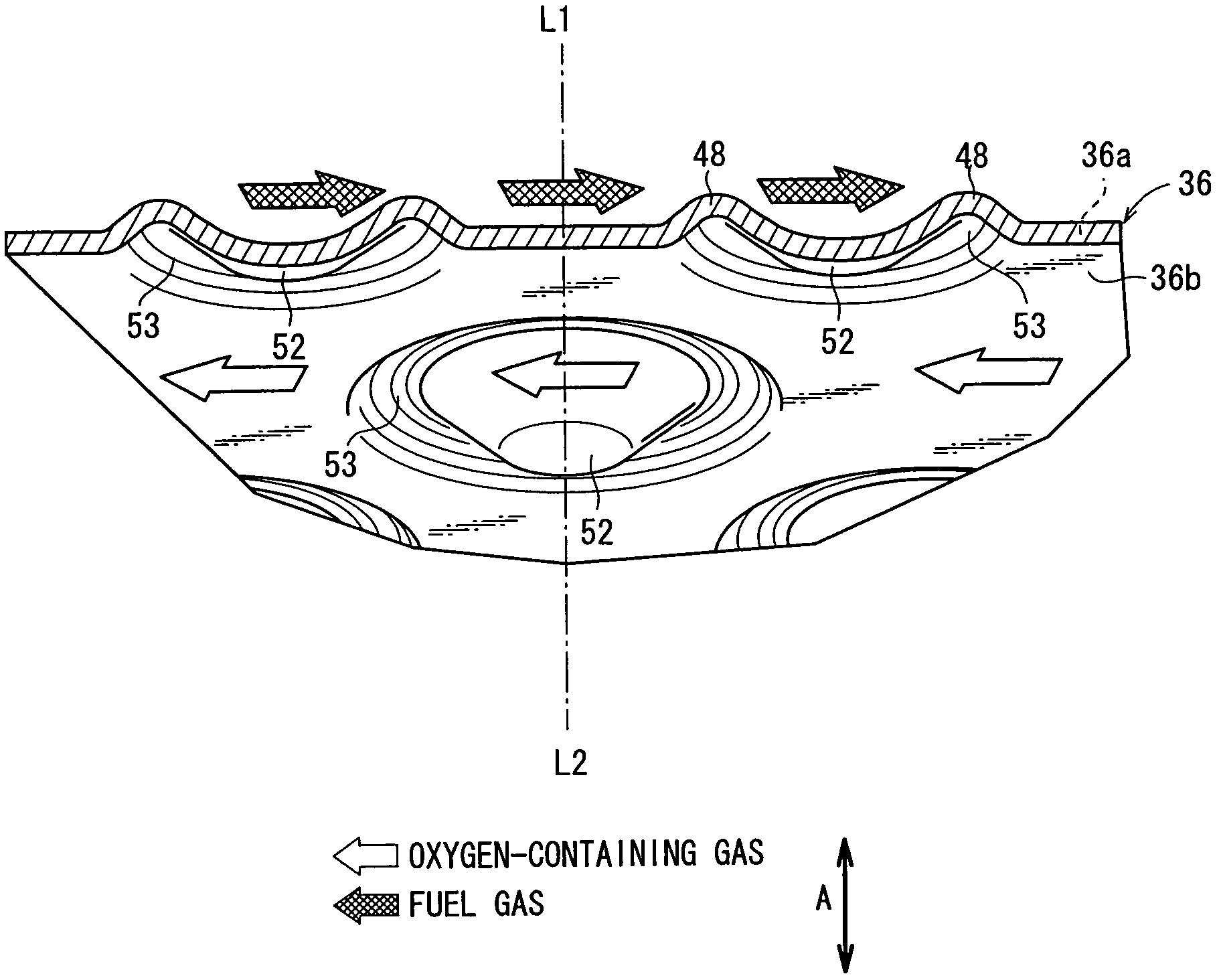
[0082]In the first and second embodiments, as shown in FIG. 7, the first protrusion 48 has a ring shape perfectly circular (annular shape). Alternatively, for example, as shown in FIG. 15, the first protrusion 48 (recess 53) may have an oval ring shape. In this case, assuming that the intersection of the major diameter “a” and the minor diameter “b” is the center of the first protrusion 48, if an axis extending through the center matches the central axis of the second protrusion 52, “the first and second protrusions 48, 52 are coaxial”.

[0083]In an example shown in FIG. 7, the second protrusion 52 has a conical shape, and a flat surface on its top. The cross section of the seco...


PUM

PropertyMeasurementUnit
heightaaaaaaaaaa
trapezoidal shapeaaaaaaaaaa
circular shapeaaaaaaaaaa

Abstract

A fuel cell includes an electrolyte electrode assembly and a pair of separators sandwiching the electrolyte electrode assembly. Each of the separators is a single plate, and includes a plurality of circular disks. First protrusions and second protrusions are provided on both surfaces of the circular disk. The first protrusions contact the anode of the electrolyte electrode assembly to form a fuel gas flow field, and the second protrusions contact the cathode of the electrolyte electrode assembly to form an oxygen-containing gas flow field. The shape of the first protrusion is different from the shape of the second protrusion. The first and second protrusions are coaxial with each other.

Description

BACKGROUND OF THE INVENTION[0001]1. Field of the Invention[0002]The present invention relates to a fuel cell including an electrolyte electrode assembly and a pair of separators sandwiching the electrolyte electrode assembly. The electrolyte electrode assembly includes an anode, a cathode, and an electrolyte interposed between the anode and the cathode.[0003]2. Description of the Related Art[0004]Typically, a solid oxide fuel cell (SOFC) employs an electrolyte of ion-conductive solid oxide such as stabilized zirconia. The electrolyte is interposed between an anode and a cathode to form an electrolyte electrode assembly (unit cell). The electrolyte electrode assembly is interposed between separators (bipolar plates). In use, a predetermined numbers of the unit cells and the separators are stacked together to form a fuel cell stack.[0005]In the fuel cell, an oxygen-containing gas or air is supplied to the cathode. The oxygen in the oxygen-containing gas is ionized at the interface bet...

Claims


Application Information

Patent Timeline
Patent Type & Authority Patents(United States)
IPC IPC(8): H01M8/04H01M8/02H01M8/24
CPCH01M8/0247H01M8/025H01M8/2425Y02E60/50H01M8/2432H01M8/2483H01M8/0258H01M8/243
Inventor HOMMA, HIROKI
Owner HONDA MOTOR CO LTD
Why Eureka
Try Eureka