
Optical bench for a mass spectrometer system

a mass spectrometer and optical bench technology, applied in the field of assembly of ion optic elements on the optical bench for mass spectrometer systems, can solve the problems of loss of signal, too small ion current for practical applications, etc., and achieve the effect of improving drawing legibility

Active Publication Date: 2008-10-28
O I CORP
View PDF18 Cites 20 Cited by
  • Summary
  • Abstract
  • Description
  • Claims
  • Application Information

AI Technical Summary

Benefits of technology

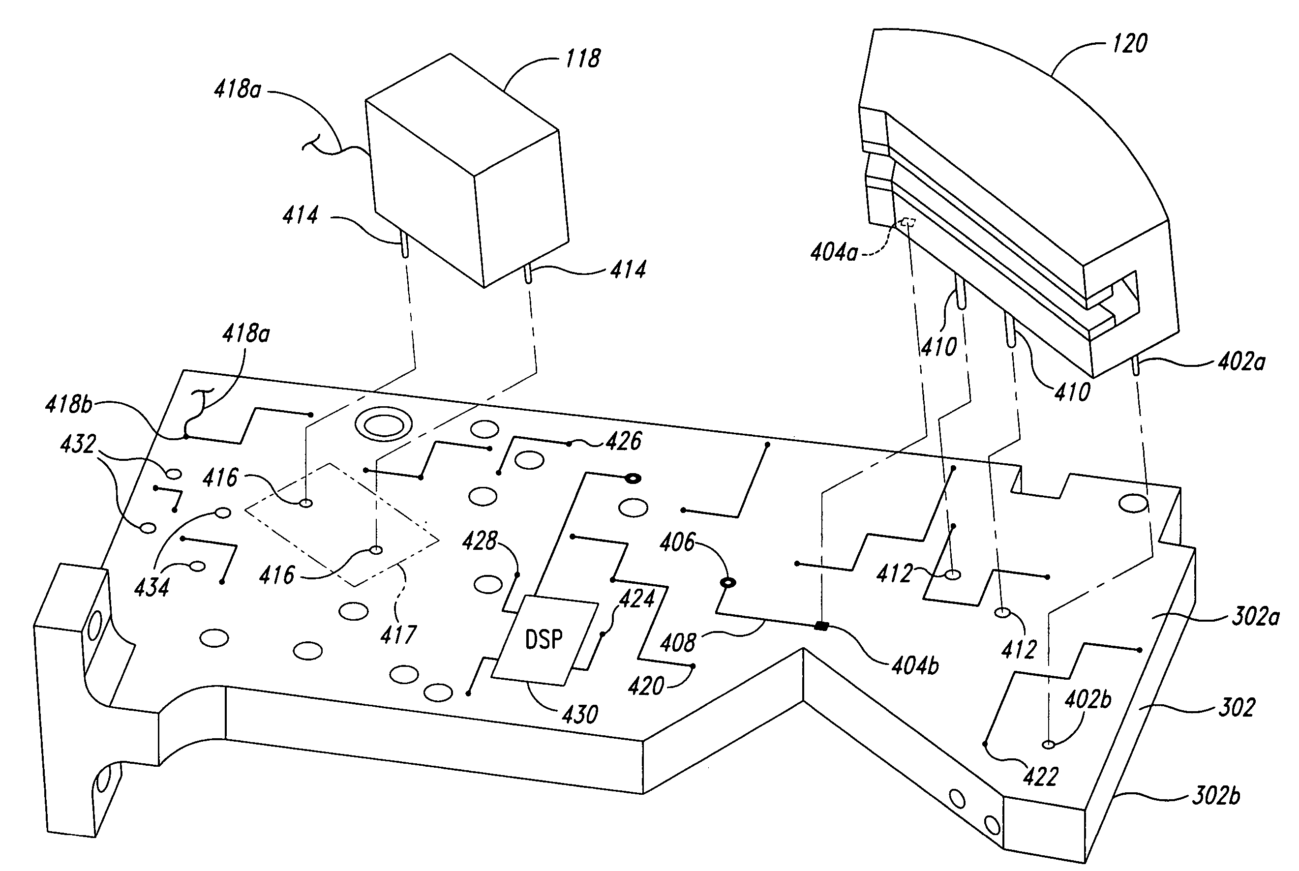
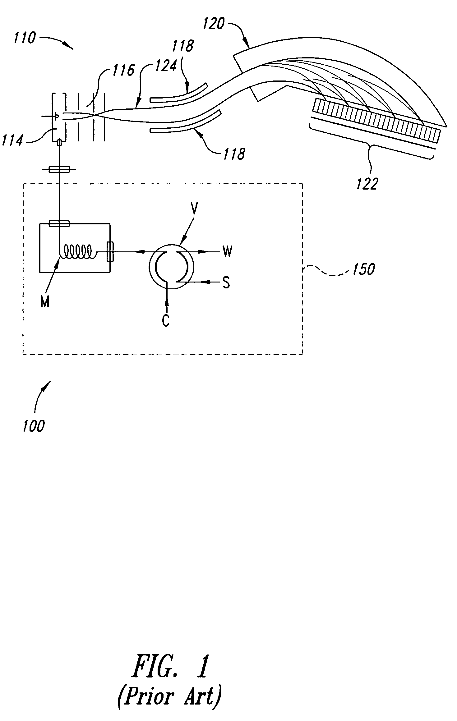
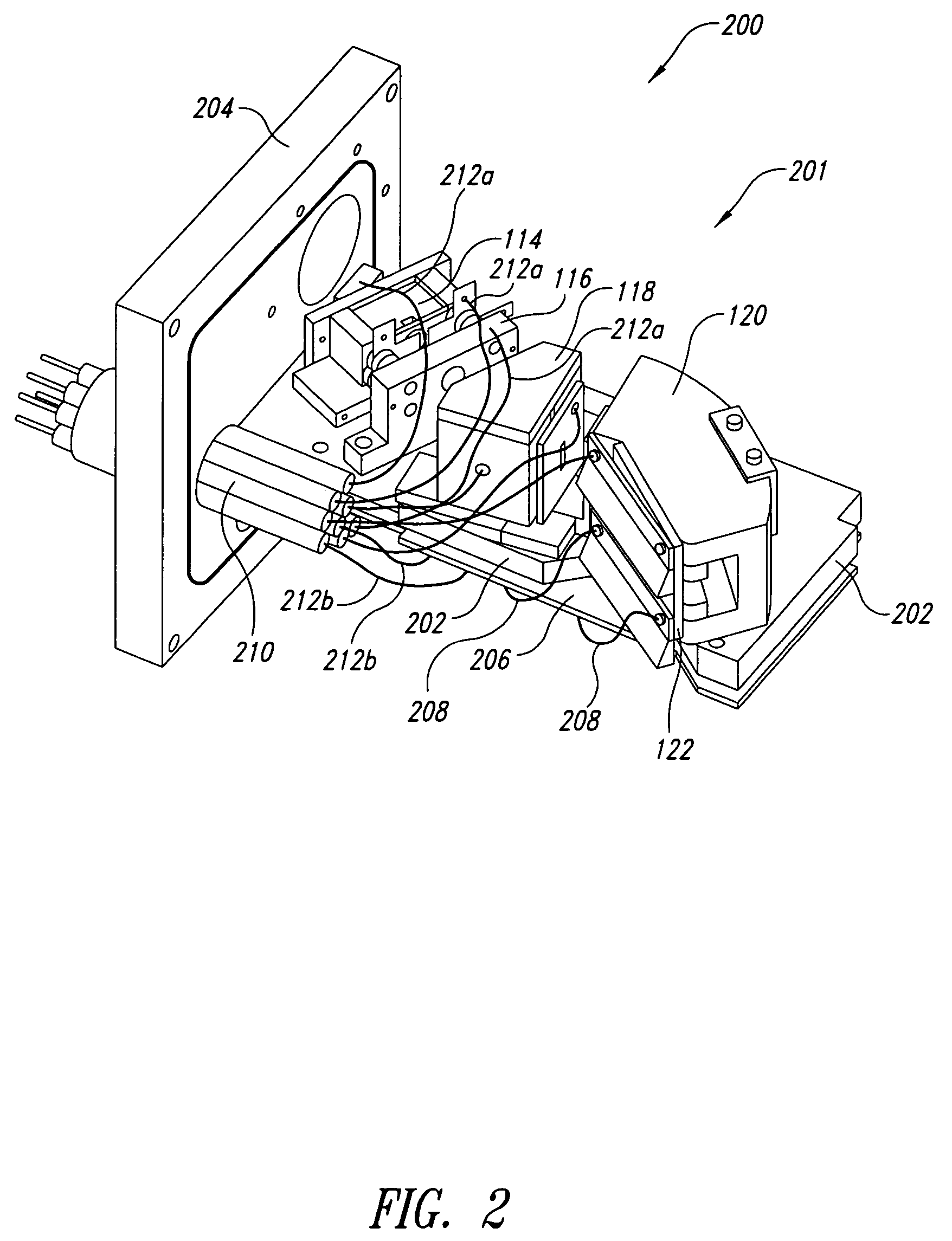
"The patent describes a mass spectrometer system that includes a vacuum flange, a PCB base plate, and an ion optic assembly. The system also includes an electrical cable for supplying power to the ion optic assembly. The PCB base plate has signal-processing electronics for processing signals received from the ion optic assembly. The system may also include a vacuum housing for enclosing the PCB base plate and the ion optic assembly. The ion optic assembly includes an ionizer, electrostatic energy analyzer, magnetic section, and detector. The printed circuit board has a first portion with mounting holes for mounting a first ion optic element and a second portion with mounting holes for mounting a second ion optic element. The first and second portions form a part of an ion beam path. The technical effects of the patent include improved vacuum stability, efficient ion optic assembly, and improved signal processing."

Problems solved by technology

Thus too small of an object slit may lead to ion currents which are too small for practical applications.
A larger microbore column M bore requires a larger vacuum pump, whereas a smaller bore produces narrower peaks of the effluent, which may result in a loss of signal.

Method used


Image

  • Optical bench for a mass spectrometer system
  • Optical bench for a mass spectrometer system
  • Optical bench for a mass spectrometer system

Examples


Embodiment Construction

[0047]In the following description, certain specific details are set forth in order to provide a thorough understanding of various disclosed embodiments. However, one skilled in the relevant art will recognize that embodiments may be practiced without one or more of these specific details, or with other methods, components, materials, etc. In other instances, well-known structures associated with mass spectrometer instruments have not been shown or described in detail to avoid unnecessarily obscuring descriptions of the embodiments.

[0048]Unless the context requires otherwise, throughout the specification and claims which follow, the word “comprise” and variations thereof, such as, “comprises” and “comprising” are to be construed in an open, inclusive sense, that is as “including, but not limited to.”

[0049]Reference throughout this specification to “one embodiment” or “an embodiment” means that a particular feature, structure or characteristic described in connection with the embodim...


PUM


Abstract

Mass spectrometer systems for measuring mass / charge ratios of analytes are described. A mass spectrometer system includes a vacuum flange, a PCB base plate coupled to the vacuum flange, and an ion optic assembly coupled to the PCB base plate. The PCB base plate may include signal-processing electronics. The system may include an electrical cable coupled to the PCB base plate for supplying power, control, and I / O to the ion optic assembly and the signal processing electronics. Alternatively, a mass spectrometer system includes a PCB base plate and an ion optic assembly. The PCB base plate has a sealant portion and an electrical portion. The ion optic assembly is coupled to the electrical portion. The system may include a vacuum housing for enclosing the ion optic assembly. The vacuum housing is coupled to the sealant portion of the PCB base plate for sustaining a vacuum while the system is in operation.

Description

CROSS-REFERENCE TO RELATED APPLICATION[0001]This application claims the benefit of U.S. Provisional Patent Application Nos. 60 / 601,803 filed on Aug. 16, 2004, 60 / 601,810 filed on Aug. 16, 2004, and 60 / 601,867 filed on Aug. 16, 2004.BACKGROUND OF THE INVENTION[0002]1. Field of the Invention[0003]This disclosure pertains to assemblies of ion optics and more particularly to assemblies of ion optic elements on an optical bench for mass spectrometer systems. 2. Description of the Related Art[0004]Mass spectrometry is widely used in many applications ranging from process monitoring to life sciences. Over the course of the last 60 years, a wide variety of instruments have been developed. The focus of new developments has been two fold: (1) a push for ever higher mass range with high mass resolution, and (2) on developing small, desktop mass spectrometry instruments.[0005]Mass spectrometers are often coupled with gas chromatographs for analysis of complex mixtures. This is particularly usef...

Claims


Application Information

Patent Timeline
Patent Type & Authority Patents(United States)
IPC IPC(8): B01D59/44
CPCH01J49/02H01J49/28H05K1/0271H05K1/0284H05K2201/2009
Inventor SCHEIDEMANN, ADI A.MCGRAW, MARK S.LONG, CLARE R.KIBELKA, GOTTFRIED P.
Owner O I CORP
Learn More