Phase shift circuit and phase correcting method

a phase shift circuit and phase correction technology, applied in pulse manipulation, pulse technique, waveguides, etc., can solve the problems of unable to obtain 45° phase difference, circuit may possibly be saturated to stop its operation, and it is extremely difficult to constantly obtain sufficient accuracy of a phase difference of signals over a wide band

Active Publication Date: 2008-10-28
SOCIONEXT INC
View PDF11 Cites 4 Cited by
  • Summary
  • Abstract
  • Description
  • Claims
  • Application Information

AI Technical Summary

Benefits of technology

[0018]It is an object of the present invention to provide a phase shift circuit outputting a plurality of signals accurately having a 45° phase difference, and a phase correcting method.
[0020]According to the present invention, by the vector synthesis of the respective first and second signals of a first set of orthogonal signals which are supposed to have a 45° phase difference relative to respective first and second signals of a second set, out of the plural sets of orthogonal phase signals having undergone the 90° phase correction, it is possible to eliminate a phase error between the respective first and second signals of the orthogonal phase signals of the different sets, to correct their phase difference to an accurate 45°.

Problems solved by technology

Consequently, a DC offset occurs due to local self-mixing using the signals with the same frequency, and by this DC offset, a subsequent-stage circuit may possibly be saturated to stop its operation.
Therefore, even if the primary CR-type 45° phase shifter 64 is designed so that a desired frequency characteristic is obtained, the resistance values of the resistors and the capacitance values of the capacitors are actually influenced by manufacturing (process) variation and parasitic components, so that a 45° phase difference cannot be obtained, or a phase error occurs because the frequency for which the phase difference becomes 45° is shifted.
However, in a conventional method, it is extremely difficult to constantly obtain sufficient accuracy of a phase difference of signals over a wide band, due to manufacturing variation or the like of resistors and capacitors constituting a phase shifter or the like.
However, this method cannot be applied directly to 45° phase difference signals.

Method used


Image

  • Phase shift circuit and phase correcting method
  • Phase shift circuit and phase correcting method
  • Phase shift circuit and phase correcting method

Examples


first embodiment

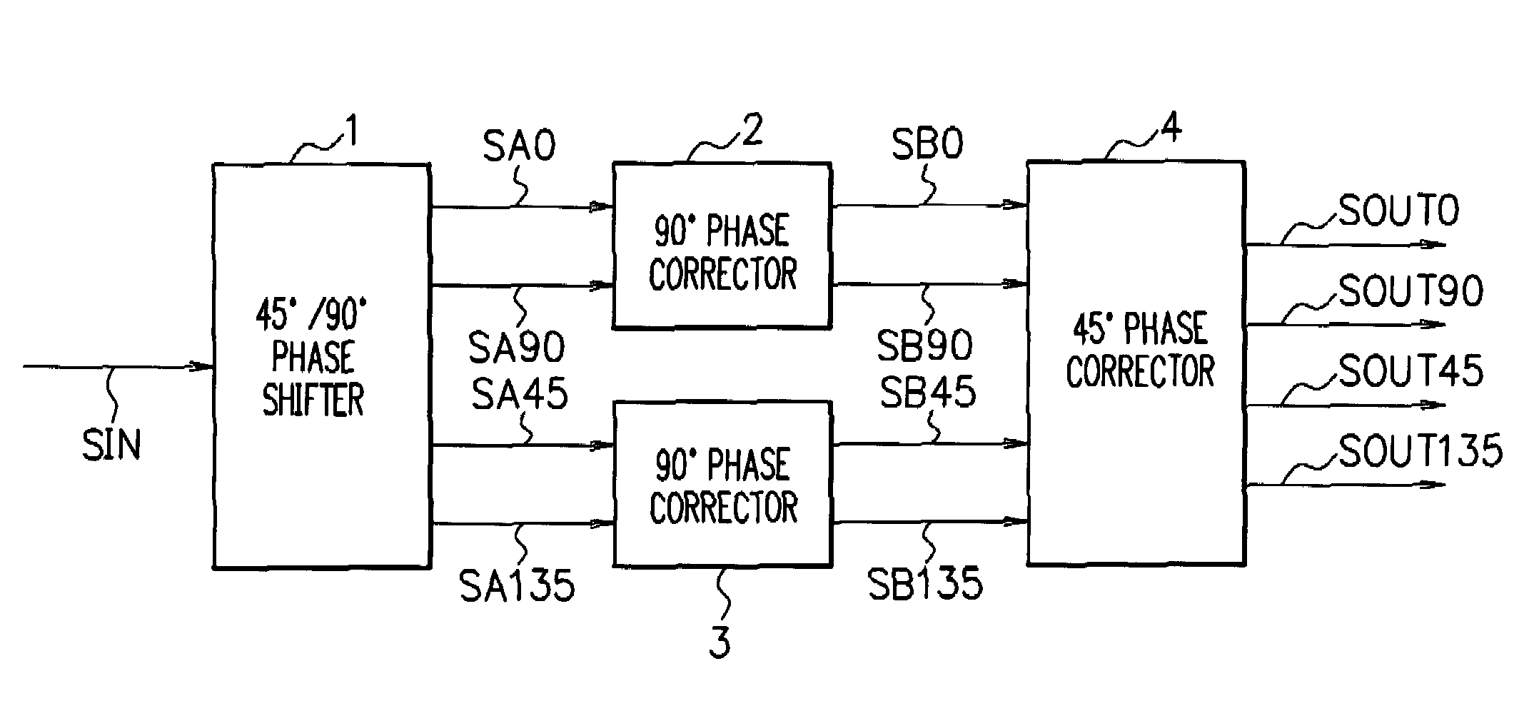
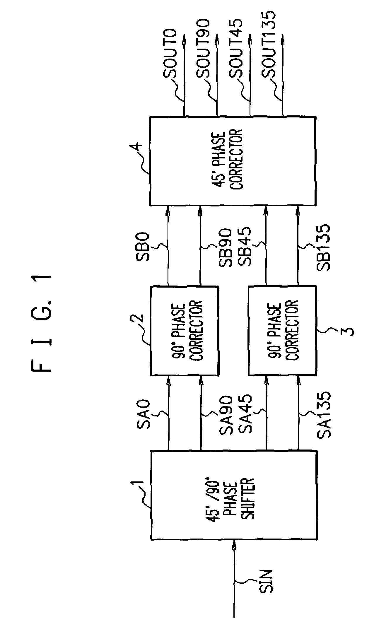
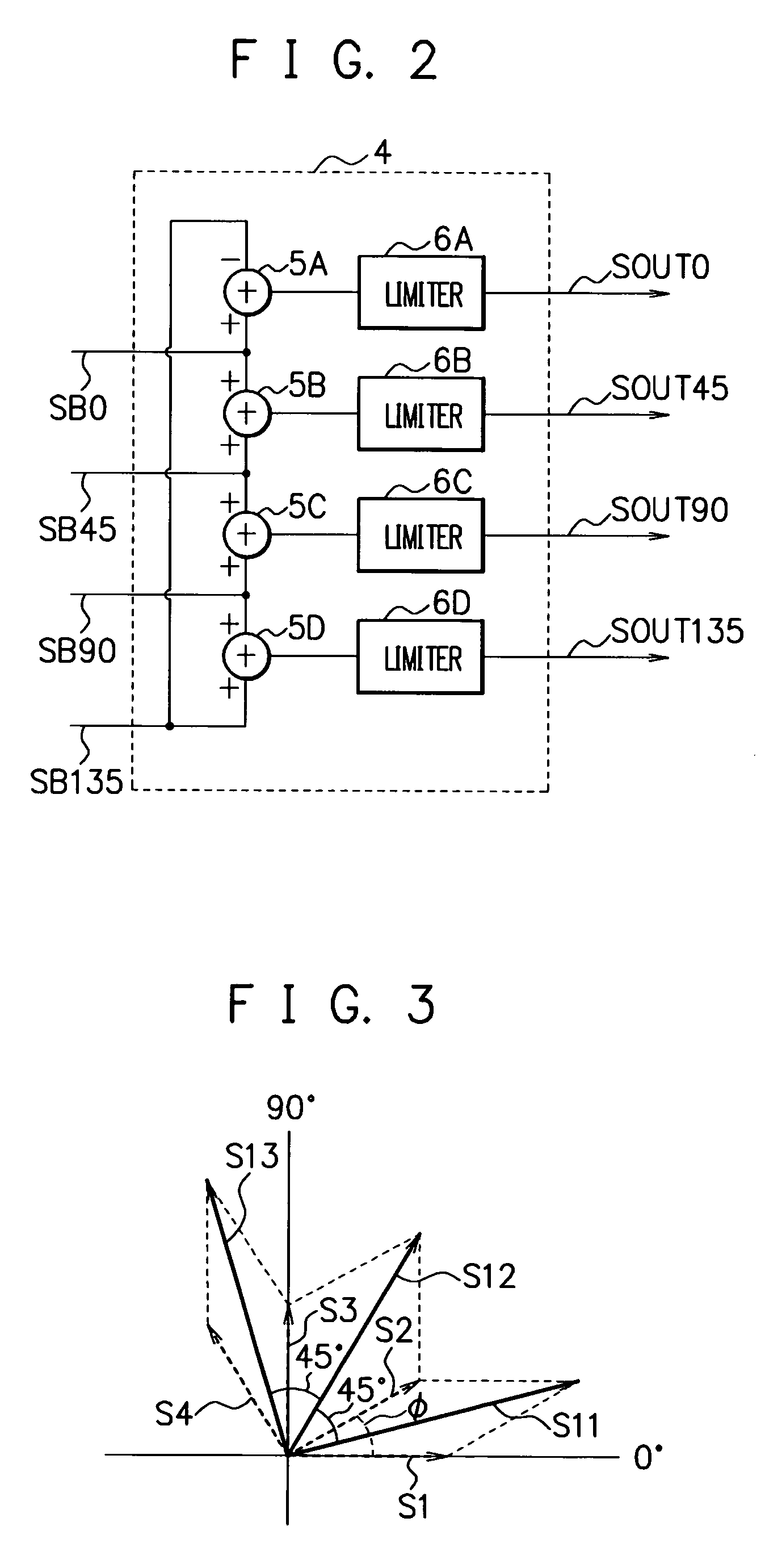
[0056]FIG. 4 is a view showing a configuration example of a 45° phase shift circuit in a first embodiment of the present invention. The 45° phase shift circuit has a 45° / 90° phase shifter 11, two 90° phase correctors 12, and a 45° phase corrector 13.

[0057]The 45° / 90° phase shifter 11 is a primary CR-LPF type 45° / 90° phase shifter for phase-shifting an input signal by an integral multiple of 45°, and receives differential input signals IN, INX to output a 0° signal SC0, a 45° signal SC45, a 90° signal SC90, and a 135° signal SC135 supposed to have 0°, 45°, 90°, and 135° relative phase differences respectively at a center frequency f0. That is, the 45° / 90° phase shifter 11 receives the differential input signals IN, INX to output the four-phase signals SC0, SC45, SC90, and SC135 with the frequency f0, having a phase difference of about 45°.

[0058]The 45° / 90° phase shifter 11 is constituted of a CR network including resistors R1˜R4 and capacitors C1˜C4, and circuits each constituted of ...

second embodiment

[0092]Next, a second embodiment will be described.

[0093]FIG. 10 is a diagram showing a configuration example of a 45° phase shift circuit in the second embodiment of the present invention. The 45° phase shift circuit in the second embodiment has a 45° phase shifter 41, 90° phase shifters 42, 43, 90° phase correctors 44, 45, and a 45° phase corrector 46.

[0094]The 45° phase shifter 41 is a primary CR-type 45° phase shifter constituted of a CR network, in which circuits each constituted of one resistor Ri and one capacitor Ci (i=any integer out of 41-44) connected in series are connected in parallel between signal lines through which differential input signals IN, INX are inputted.

[0095]The 45° phase shifter 41 receives the differential input signals IN, INX to output a 0° signal SF0, a 45° signal SF45, a 180°signal SF180, and a 225° signal SF225 which are supposed to have 0°, 45°, 180°, and 225° relative phase differences respectively. Incidentally, resistance values of the resistors ...


PUM


Abstract

A phase shift circuit includes a 45° phase corrector that performs vector synthesis of signals supposed to have a 45° phase difference, out of a plurality of sets of orthogonal phase signals having an about 45° phase difference and an equal amplitude, the orthogonal phase signals in each set having undergone 90° phase correction, and outputs signals resulting from the vector synthesis, whereby a phase error between the orthogonal phase signals in the different sets is eliminated by the vector synthesis to make it possible to correct their phase difference to accurately 45°.

Description

[0001]This application is a continuing application, filed under 35 U.S.C. §111(a), of International Application PCT / JP2004 / 010030, filed Jul. 14, 2004, the contents of which are incorporated herein by reference.TECHNICAL FIELD[0002]The present invention relates to a phase shift circuit and a phase correcting method, more particularly, to those suitably applied to a 45° phase shift circuit that generates a plurality of signals having a 45° phase difference.BACKGROUND ART[0003]In a receiver and the like for wireless communication such as mobile communication, a direct conversion (zero IF) method is a desirable reception method. Being simple in circuit configuration and requiring no IF (Intermediate Frequency) filter, the direct conversion method can realize cost reduction.[0004]However, a typical direct conversion receiver that has been conventionally used mixes local oscillation signals having the same frequency as that of an inputted high-frequency signal (reception signal) to take ...

Claims


Application Information

Patent Timeline
Patent Type & Authority Patents(United States)
IPC IPC(8): H03H11/16
CPCH03H7/21
Inventor TOMITA, KAZUHIRO
Owner SOCIONEXT INC
Why Eureka
Try Eureka