
Time delay apparatus and method of using same

a time delay and generator technology, applied in pulse manipulation, pulse technique, instruments, etc., can solve the problems of significant phase noise in the prior non-linear time delay response in the prior art gilbert cell time delay generator, and external noise on the analog control signal introducing phase noise in the prior art time delay generator

Active Publication Date: 2008-11-04
HRL LAB
View PDF10 Cites 3 Cited by
  • Summary
  • Abstract
  • Description
  • Claims
  • Application Information

AI Technical Summary

Benefits of technology

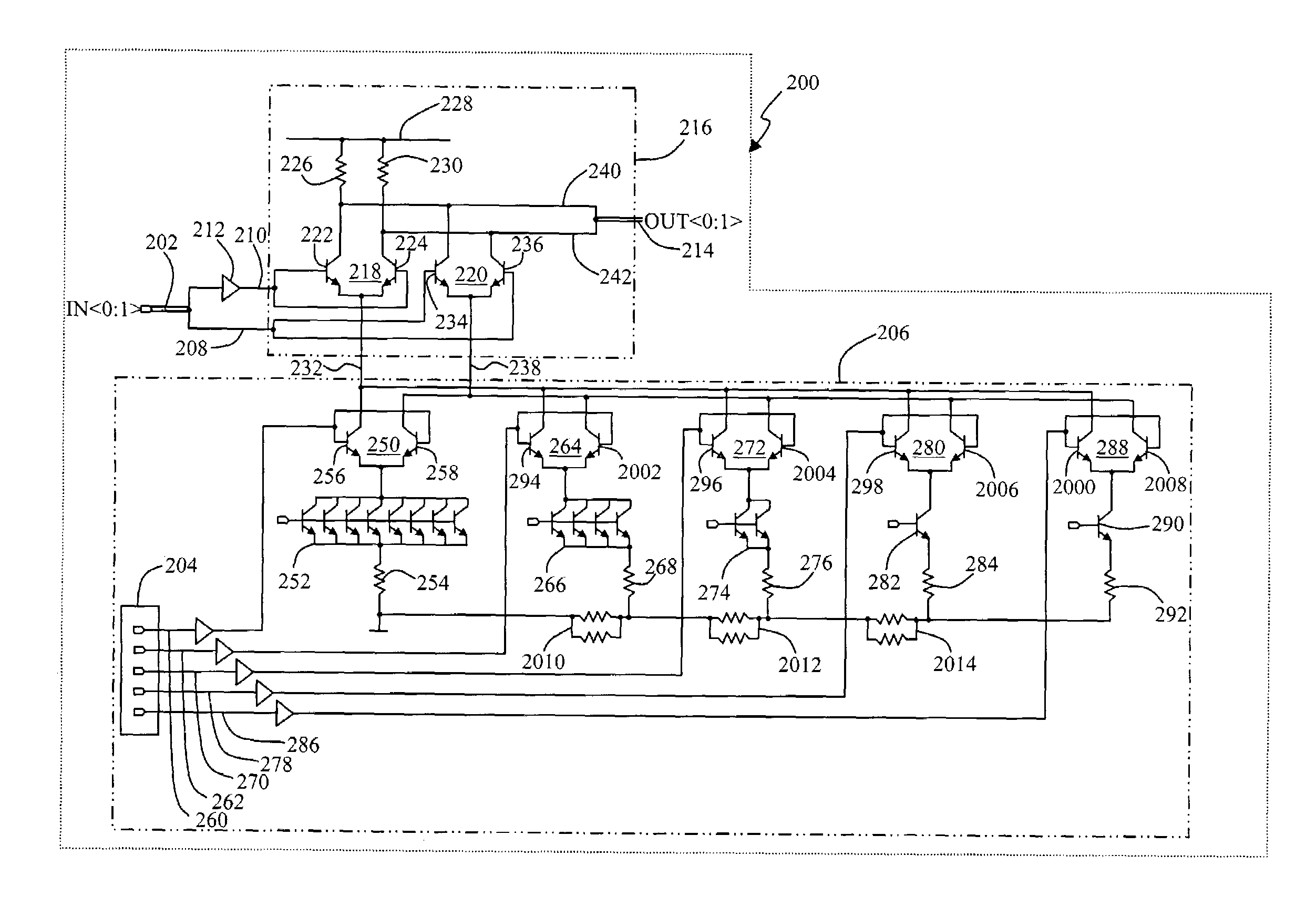
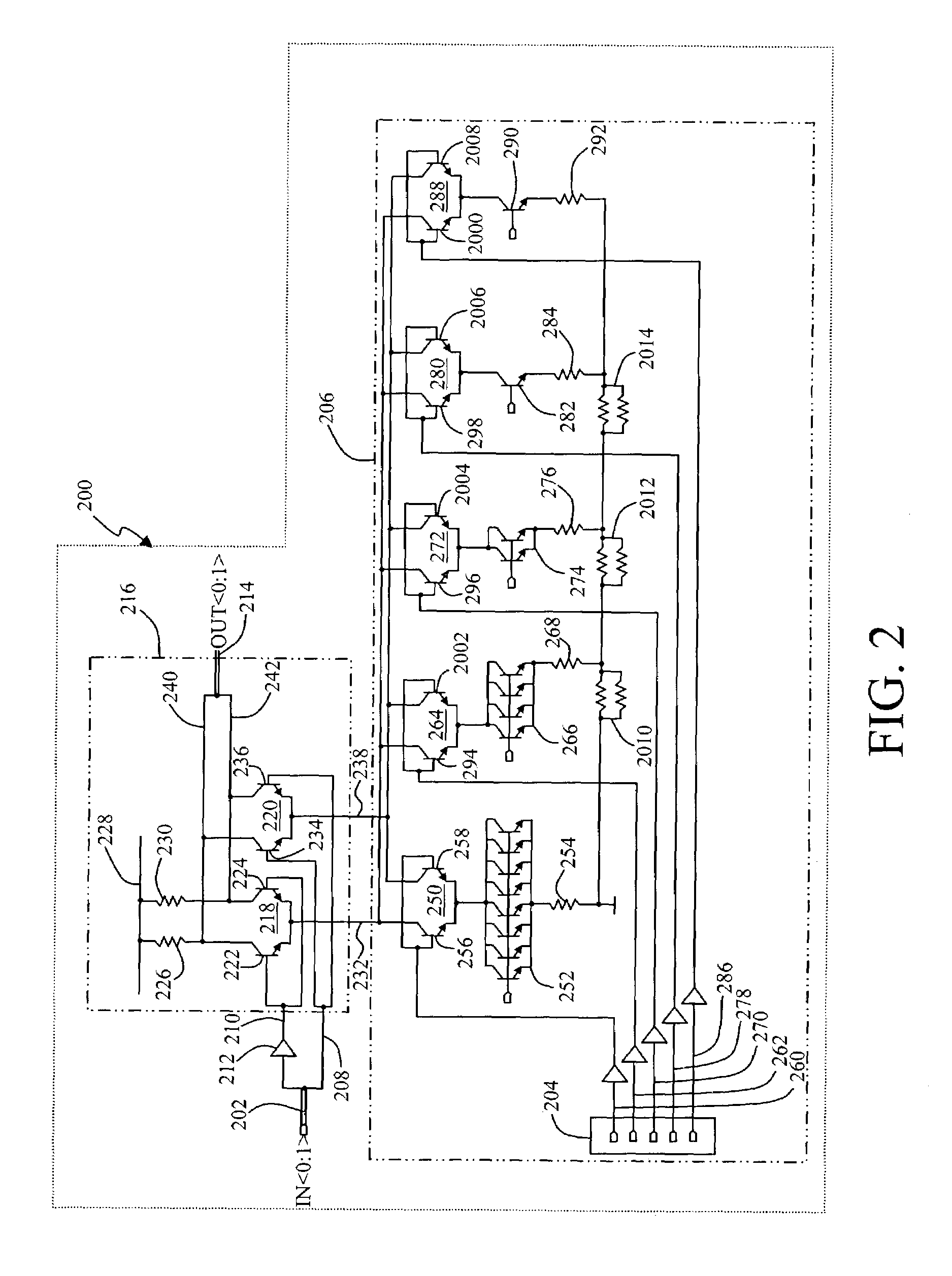
The present invention provides an apparatus for generating a variable time delay to produce a delayed output signal with a time delay governed by a digital signal input. The apparatus includes delaying means for generating a delayed input signal, a digital to analog converter for controlling current through first and second control lines, and mixing means for generating a delayed output signal by mixing the delayed input signal and undelayed input signal in proportion to the current through the first and second control lines. The method involves inputting an undelayed input signal, generating a delayed input signal by delaying the undelayed input signal, inputting a digital word representing the time or phase delay to be applied to the undelayed input signal, and mixing the undelayed input signal and delayed input signal to produce a delayed output signal with a time or phase delay substantially related to the digital word. The time delay generator is operable at radio frequencies, gigahertz frequencies, and above. It has phase resolution of less than one picosecond, and the signal delaying means provides a delay that is on the order of less than 100 picoseconds.

Problems solved by technology

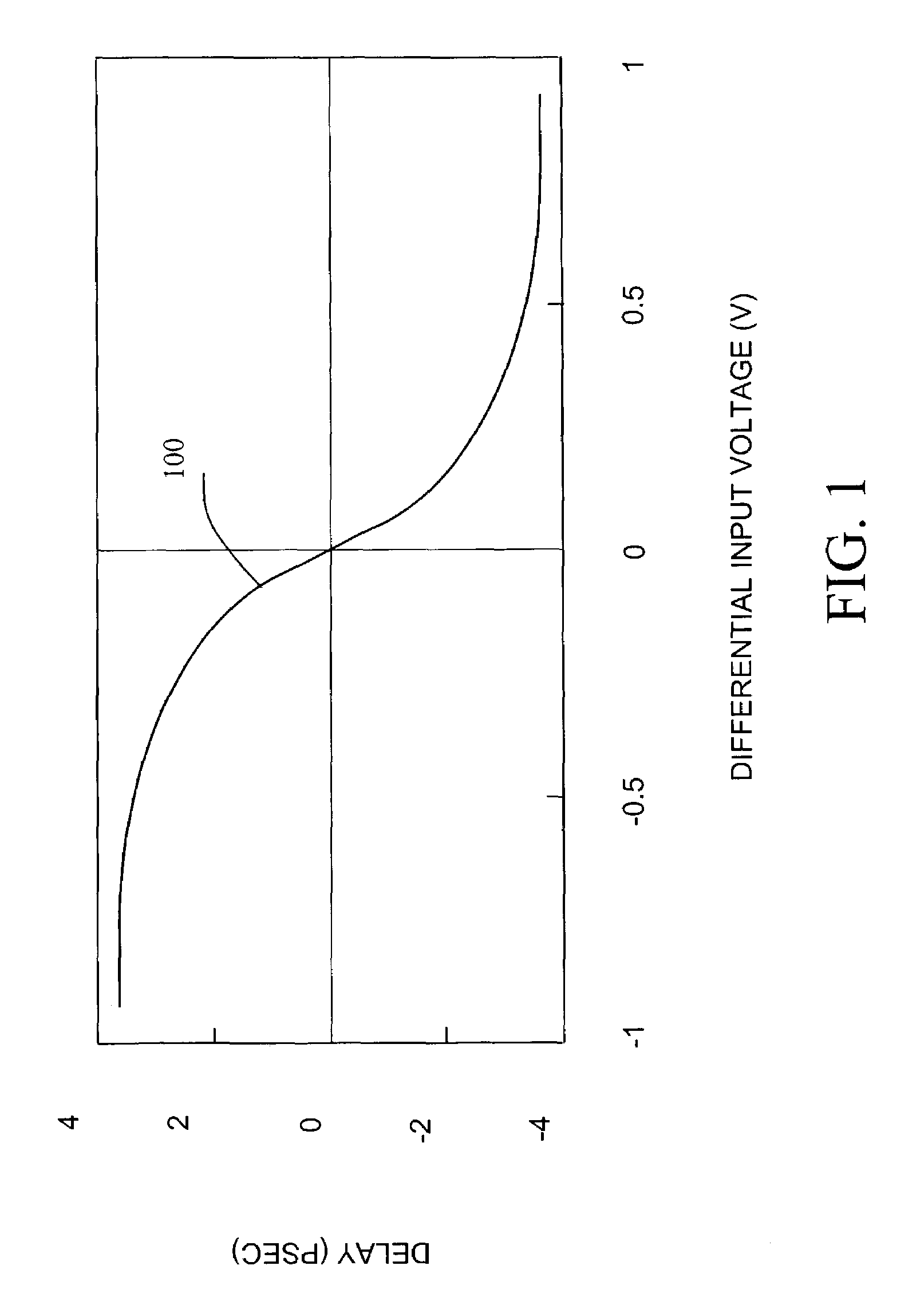
First, the time delay response in the prior art Gilbert cell time delay generators is non-linear, often requiring a pre-distortion stage to compensate and correct the analog control signal.
Second, external noise on the analog control signal introduces phase noise in prior art time delay generators.
The degradation in phase resolution is significant and is commonly the limiting factor in the performance of high frequency time delay generators operating in and above the microwave band.

Method used


Image

  • Time delay apparatus and method of using same
  • Time delay apparatus and method of using same
  • Time delay apparatus and method of using same

Examples


Embodiment Construction

[0013]The present invention provides a method and an apparatus for generating a delayed output signal, with respect to an input signal, having a variable time delay governed by a digital signal input. The following description, taken in conjunction with the referenced drawings, is presented to enable one of ordinary skill in the art to make and use the invention and to incorporate it in the context of particular applications. Various modifications, as well as a variety of uses in different applications, will be readily apparent to those skilled in the art, and the general principles defined herein may be applied to a wide range of aspects. Thus, the present invention is not intended to be limited to the aspect presented, but is to be accorded the widest scope with the principles and novel features disclosed herein. Furthermore, it should be noted that unless explicitly stated otherwise, the figures included herein are illustrated diagrammatically and without any specific scale, as t...


PUM


Abstract

Disclosed is a time delay generator 200 apparatus and method. The apparatus includes a time delay gate 212, a mixer 216 (a Gilbert cell circuit), and a current digital to analog converter 206. The mixer 216, comprised of first and second transistor differential pairs 218 and 220, receives an analog input signal 202 without a delay as well as a delayed input signal 210 produced by the time gate delay. The digital to analog converter regulates the relative current flow between a first control signal 232 and a second control signal 238, effectively altering the mixing of the undelayed input signal 208 and the delayed input signal 210 to generate a delayed output signal 214 with a time or phase delay substantially equal to the temporal delay represented by the digital signal input 204. The time delay generator exhibits reduced phase noise and a linear time delay response.

Description

STATEMENT OF GOVERNMENT RIGHTS[0001]Elements of this invention were made with U.S. Government support from the Defense Advanced Research Projects Agency, under Government Contract Number N00014-99-C-0159. The U.S. Government may have certain rights in this invention.TECHNICAL FIELD[0002]The present invention relates to a true time delay generator. More specifically, the present invention relates to an apparatus and method for generating a true time delay using a Gilbert cell circuit with digital to analog converter control.BACKGROUND[0003]There are a number of time delay generators known in the prior art, including those employing Gilbert cell circuit configurations. In each of the previous time delay generators, the mixing of delayed and undelayed input signals is regulated by an analog control signal coupled to the differential transistor pairs of the mixing circuit. The application of a single analog control signal causes two significant problems substantially overcome by the pre...

Claims


Application Information

Patent Timeline
Patent Type & Authority Patents(United States)
IPC IPC(8): H03H11/26H03K5/00H03K5/13H03K17/60H03K17/62
CPCH03K5/131H03K17/603H03K17/6264H03K2005/00176H03K2005/00065
Inventor ELLIOTT, KENMORTON, SUSANRODWELL, MARK
Owner HRL LAB
Learn More