Atomic frequency acquiring apparatus and atomic clock

a technology of atomic clocks and acquisition apparatuses, applied in the field ofatomic frequency acquisition apparatuses and atomic clocks, can solve the problems of low mass production efficiency of electronic apparatuses that incorporate atomic clocks, and achieve the effect of improving mass production efficiency

Active Publication Date: 2008-11-04
MICROCHIP TECH INC
View PDF3 Cites 7 Cited by
  • Summary
  • Abstract
  • Description
  • Claims
  • Application Information

AI Technical Summary

Benefits of technology

[0006]In accordance with an advantage of some aspects of the present invention, atomic clocks can be made smaller in size, and their mass production efficiency can be improved.
[0011]According to the embodiments of the invention, the cell, the laser light source and the photodetection section are integrated into one piece, such that the apparatus can be made smaller in size. Also, the components do not need to be independently installed on the substrate such that position alignment of the components is not required, which can improve the mass production efficiency of the apparatus.
[0012]Also, because the laser light source is disposed inside the cell, a loss that may be caused by reflection of laser light at an incident surface of the cell can be prevented. Similarly, because the photodetection section is disposed inside the cell, a loss that may be caused by reflection of laser light at an emission surface of the cell can be prevented. As a result, the utilization efficiency of laser light can be improved.
[0015]As a result, the laser light source and the photodetection section can be prevented from deterioration by the gas inside the cell.

Problems solved by technology

The complexity in alignment works is one of the causes that lower the mass production efficiency in manufacturing electronic apparatuses that incorporate atomic clocks.

Method used


Image

  • Atomic frequency acquiring apparatus and atomic clock
  • Atomic frequency acquiring apparatus and atomic clock
  • Atomic frequency acquiring apparatus and atomic clock

Examples


embodiment 1

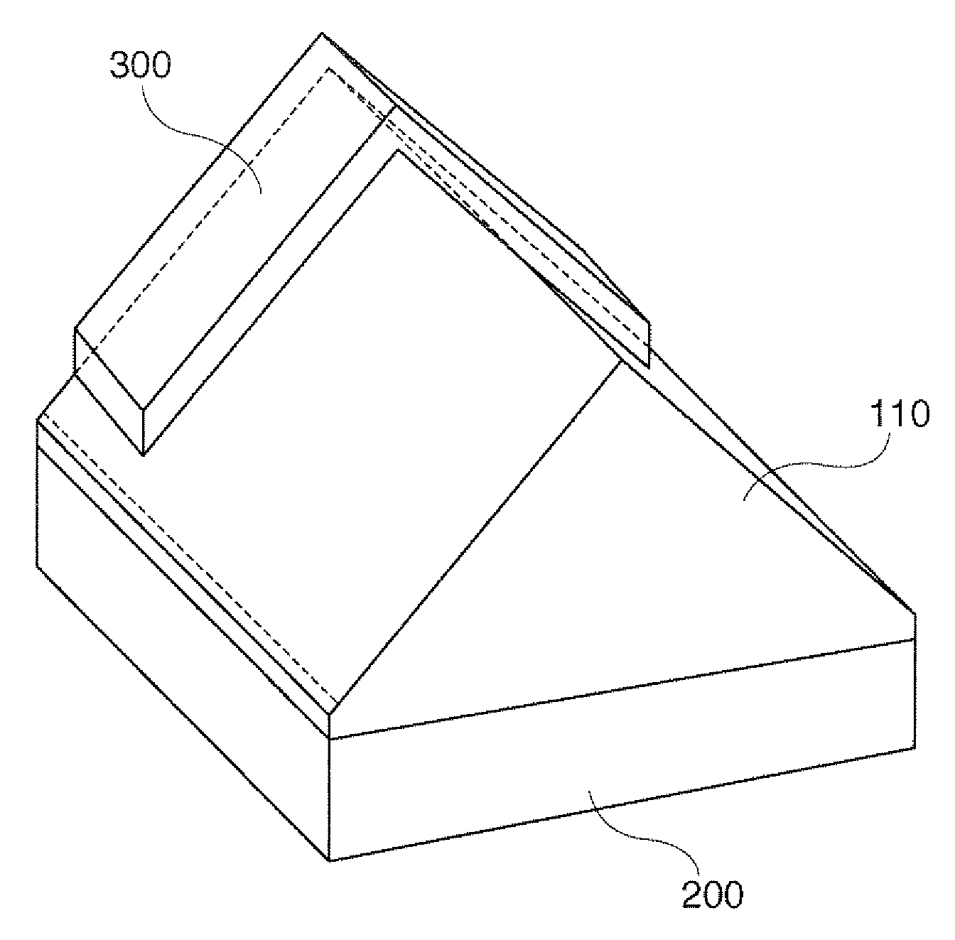
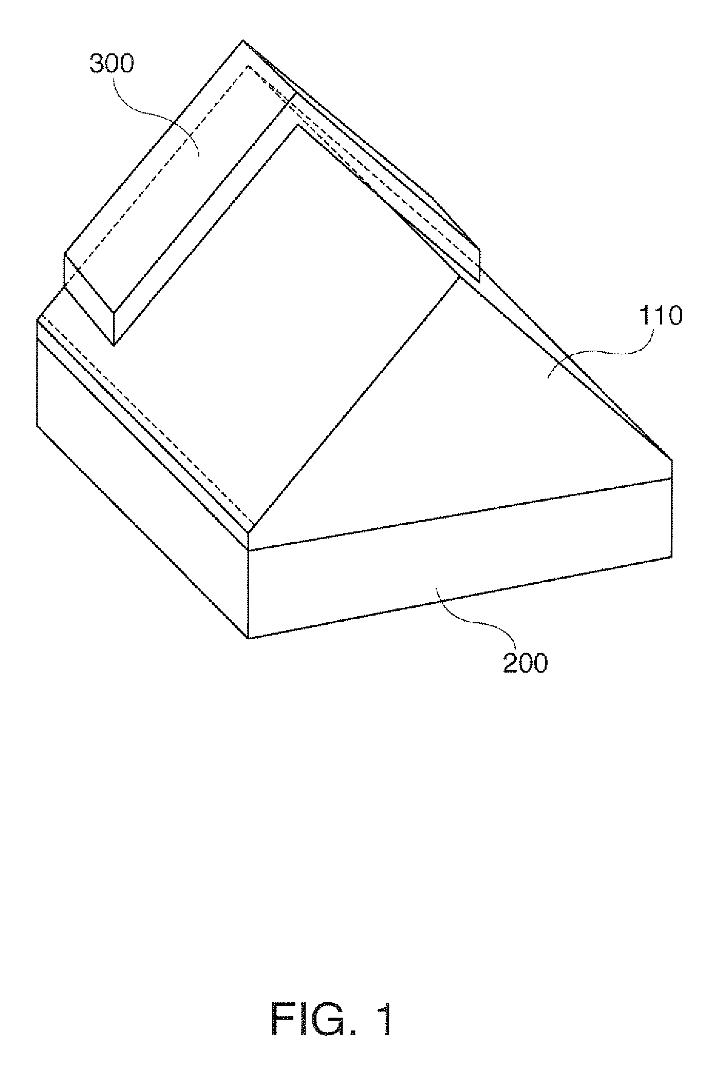
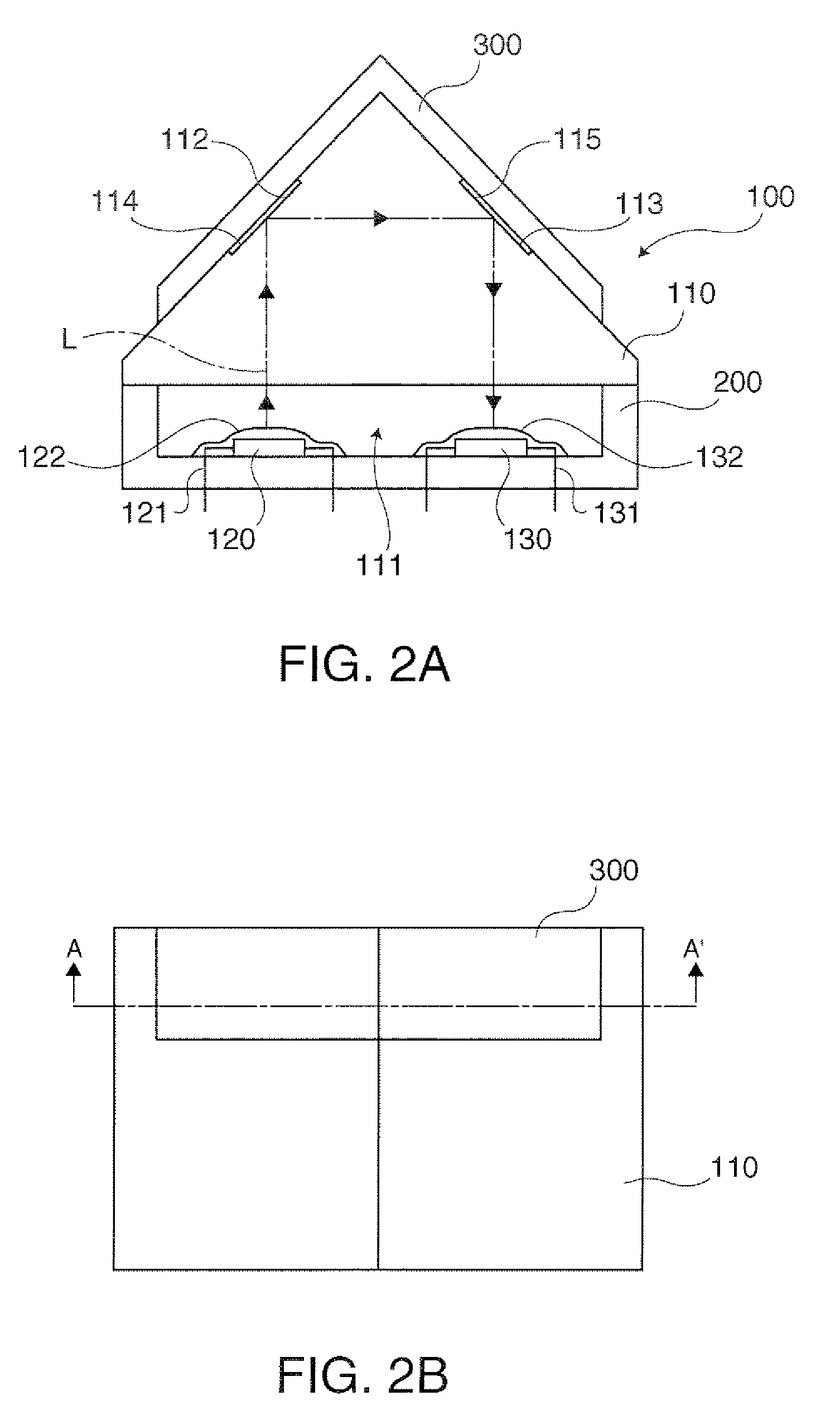
[0026]FIG. 1 is a perspective view of the structure of an atomic frequency acquisition apparatus 100 in accordance with an embodiment 1 of the invention. FIG. 2A is a cross-sectional view taken along a line A-A′ in FIG. 2B, and FIG. 2B is a plan view of the atomic frequency acquisition apparatus 100. The atomic frequency acquisition apparatus 100 may be used to acquire a time standard frequency in a CPT type atomic clock.

[0027]As shown in FIG. 1 and FIGS. 2A and 2B, the atomic frequency acquisition apparatus 100 is equipped with a ceramic package 200 having an opening section in a portion thereof, a sealing section 110 disposed in a manner to seal the opening section, a laser diode (i.e., a laser light source) 120 and a photodetector (photodetection section) 130. The ceramic package 200 and the sealing section 110 form a cell having a cavity (void space) 111 therein. Cesium atom gas is enclosed in the cavity 111.

[0028]The ceramic package 200 is formed with ceramics, and the sealing ...

embodiment 2

[0048]FIG. 5 is a perspective view of the structure of an atomic frequency acquisition apparatus 100 in accordance with an embodiment 2 of the invention. FIG. 6A is a cross-sectional view taken along a line A-A′ in FIG. 6B, and FIG. 6B is a plan view of the atomic frequency acquisition apparatus 100. Reference numbers that are the same as those indicated in FIGS. 1, 2A and 2B denote corresponding components. In accordance with the embodiment 2, a laser diode 120 and a photodetector 130 are disposed on opposing surfaces facing a cavity 111 of a ceramic package 200, respectively.

[0049]Laser light (L) emitted from the laser diode 120 advances straight within the cavity 111 and is detected by the photodetector 130, as shown in FIG. 6A.

[0050]According to the embodiment 2 of the invention, like the embodiment 1, the cell formed with the ceramic package 200 and the sealing section 110, the laser diode 120 and the photodetector 130 are integrated in one piece, such that the atomic frequency...


PUM


Abstract

An atomic frequency acquisition apparatus includes: a cell enclosing atomic gas therein; a laser light source that oscillates laser light that enters the cell and excites the atomic gas; and a photodetecting section that detects the laser light that has passed the cell, wherein the laser light source and the photodetecting section are attached to a common surface facing an interior of the cell, and the cell has a first reflection section on which the laser light oscillated from the laser light source is incident at an incident angle of 45 degrees, and a second reflection section on which the laser light reflected by the first reflection section is incident at an incident angle of 45 degrees.

Description

[0001]The entire disclosure of Japanese Patent Application No. 2005-367786, filed Dec. 21, 2005 is expressly incorporated by reference herein.BACKGROUND[0002]1. Technical Field[0003]The present invention relates to atomic frequency acquiring apparatuses and atomic clocks.[0004]2. Related Art[0005]Atomic clocks that control the frequency of an oscillator based on the natural frequency of atoms are more often used in various situations instead of conventional quartz oscillators. Above all, coherent population trapping (CPT) type atomic clocks are suitable for miniaturization and power-saving, and are expected to be applied to cellular phones or other devices in future. The accuracy of an atomic clock may be deteriorated unless its gas cell that encloses atomic gas, laser emission section and photodetector section are accurately aligned with one another on a substrate. The complexity in alignment works is one of the causes that lower the mass production efficiency in manufacturing elec...

Claims


Application Information

Patent Timeline
Patent Type & Authority Patents(United States)
IPC IPC(8): H03B17/00
CPCG04F5/145H01S3/1392
Inventor KOYAMA, TOMOKO
Owner MICROCHIP TECH INC
Why Eureka
Try Eureka