Sleeved optical fiber for reduced lateral loss and method for making the same

a technology of lateral loss and sleeved optical fiber, which is applied in the field of sleeved optical fiber for reducing lateral loss and making the same, can solve the problems of large cylindrical distortion of the output beam profile, significant snell reflection and large cylindrical distortion of the impracticality of ccdr for the core diameter required in laser surgery, etc., to achieve the effect of reducing reflection and cylindrical distortion

Active Publication Date: 2008-11-04
BOSTON SCI SCIMED INC +1
View PDF17 Cites 22 Cited by
  • Summary
  • Abstract
  • Description
  • Claims
  • Application Information

AI Technical Summary

Benefits of technology

[0017]The invention claimed and described herein comprises a strategy for forming short sections of high CCDR, fluorine-doped silica clad:silica core fiber (silica:silica fiber) upon either lower CCDR silica:silica fiber or upon polymer clad silica fiber. In the preferred embodiment, a tube formed of uniformly fluorine-doped silica is produced that possesses dimensions similar to the desired fiber cladding wherein the core is eliminated, where the fluorine concentration is equivalent to standard fiber cladding. A polymer clad fiber is stripped of cladding for a short length at one terminus. The relatively close fitting, fluorine-doped tube is positioned over the bare core and is fused into place entirely about the circumference of the fiber by thermal collapse, effectively forming a section of silica:silica fiber.
[0020]The art disclosed herein offers flexibility in fiber design in addition to cost reduction and ease of execution. Where a fusion spliced version of Pon may only be made using the few fiber CCDRs that are offered commercially—1.05, 1.1, 1.2 and 1.4—the fluorine-doped or pure silica tubing disclosed herein may be made to virtually any dimensions imaginable, at very low cost. Further in contrast to prior art, the invention disclosed herein provides all of the reductions in reflections and cylindrical distortions of Pon while using low cost fiber in a manner where core and dimensional mismatch issues are eliminated.
[0026]To provide a new and useful construct upon which lateral diversion elements may be produced upon optical fiber that offer reduced reflection and cylindrical distortion.

Problems solved by technology

Normal contaminants in any use environment may also cause leakage if they come into contact with the reflective bevel tip of a lateral fiber.
Of course, such a CCDR is impractical for the core diameters required in laser surgery; the fiber would be approximately a 7.5 mm diameter rigid rod rather than the required flexible conduit.
For fiber constructions suitable for surgical applications, the small CCDRs required give rise to larger portions of the fiber circumference being illuminated by the reflected energy, giving rise to the amplification of Fresnel reflections, the introduction of significant Snell reflections and large cylindrical distortions of the output beam profile.
As a practical matter, the act of fusing a bare fiber into a relatively massive protective cap melts the reflective surface slightly, resulting in some distortions in the initial reflection.
Particularly in applications where energy densities within the fiber are especially high and where the light acting upon the target produces great amounts of heat, for example in pulse laser surgical applications, the fused strategies disclosed by Griffin and Brekke fail due to rapid thermal expansion and contraction.
The fusion processes result in local stresses within the composite silica structures that are prone to fracture when exposed to extreme temperature differences.
In short, the total energies that may safely be used within the art disclosed by Brekke and Griffin are limited due to these residual stresses.
The art disclosed in Pon is practically limited by the minimal options available in fiber CCDR (as well as other dimensional design constraints) to a fiber cladding diameter that is 1.4-fold the core diameter.
A 1.6 CCDR fiber would perform better than the 1.4 CCDR fiber disclosed in Pon, but the costs of producing such fiber are incompatible with the needs of the surgical application because the 1.6 CCDR preforms required are non-standard and would be extremely costly to produce.
The art in Pon is, in fact, limited by these economic considerations.
Further, use of larger CCDR fiber throughout a device limits the flexibility wherein flexibility is desirable.
Unfortunately, where communications optical fiber is extremely precise in core and cladding dimensions (with a dimensional tolerance of less than 1% on relatively small overall diameters, typically 125 μm), the dimensions of the large core, multimode fiber used in surgical devices is less reproducible at typically 2% tolerance on the cladding diameter.
Mating cores that vary by as much as 25 μm between the low cost, 1.1 CCDR fiber and the costly 1.4 CCDR fiber introduces severe complications.
The severe mismatch in glass diameters between the low cost fiber and the high CCDR fiber introduces additional difficulties in producing efficient fusion splices.
Where the inverse is the case, light exiting the larger trunk core will enter the 1.4 CCDR fiber (lateral emission section) cladding, rendering the Fresnel and Snell reflection reduction strategy ineffective for these cladding modes.
This strategy preserves the reflection reduction strategy but introduces new complications in device design by increases the physical dimension mismatch issues and the overall size of the lateral emissions section by ˜4% or reducing the available core diameter for input of the laser energy.
Beyond dimensional mismatch of the trunk and lateral emission section cores, precise physical alignment of the cores is also necessary and physical alignment of extremely different diameter materials is far more challenging that matching identical diameters.

Method used


Image

  • Sleeved optical fiber for reduced lateral loss and method for making the same
  • Sleeved optical fiber for reduced lateral loss and method for making the same
  • Sleeved optical fiber for reduced lateral loss and method for making the same

Examples


Embodiment Construction

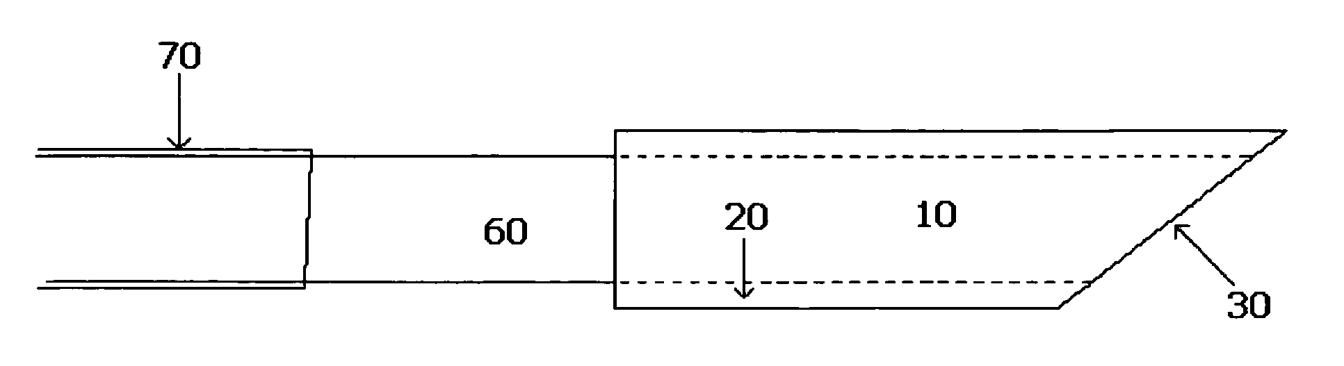
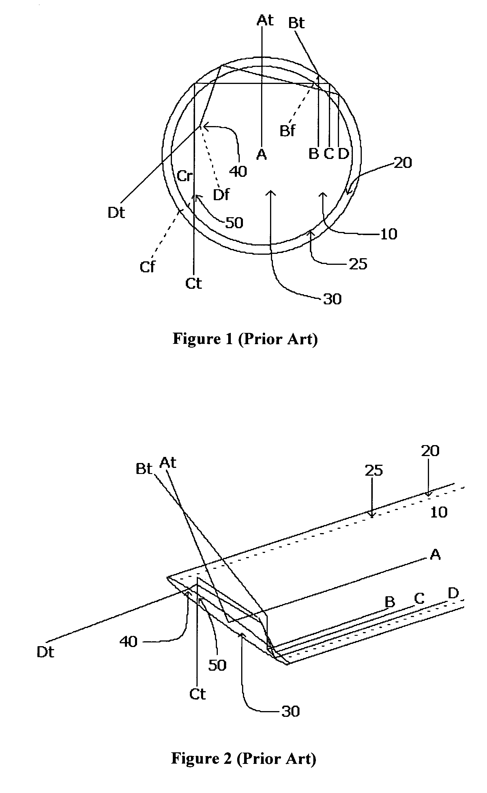
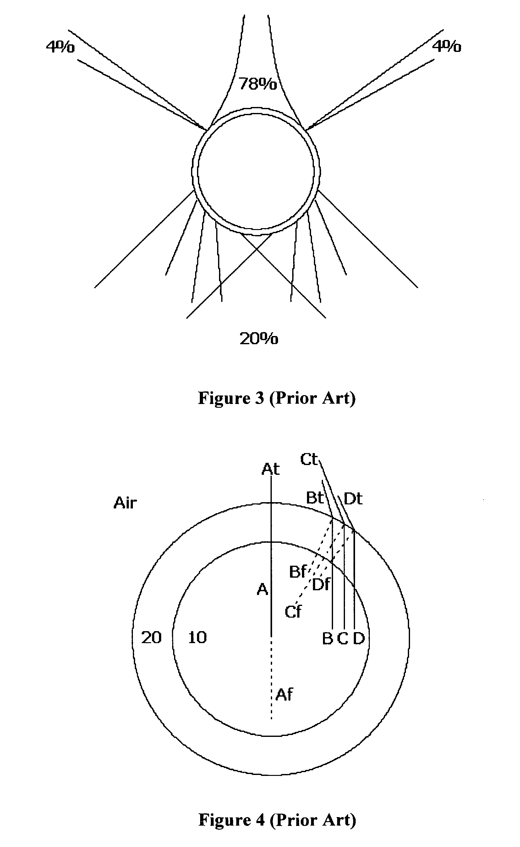
[0036]FIGS. 1 and 2 should be referred to in unison for clarity in tracing the paths of some characteristic rays within the output tip of a standard lateral fiber. The figures depict the fate of four rays, A, B, C and D that have been conducted to the beveled fiber face 30 within a standard, 1.1 CCDR fiber where the fiber core 10 of diameter X is surrounded by fluorine-doped cladding 20 of diameter 1.1X. All rays depicted are chosen to be zero order within the transmitting fiber for simplicity. In reality the extreme cases are more extreme than depicted due to the fact that higher order (angle) rays are supported within the transmitting fiber. Ray A is centered within the fiber core 10 and represents the best-case ray for the fiber design, for reference. The angle of incidence upon the fiber sidewall for ray A is essentially normal to the plane of the circumference so that the transmitted ray At is minimally refracted, there are no reflections according to Snell's Law and Fresnel re...


PUM

PropertyMeasurementUnit
diameteraaaaaaaaaa
diameteraaaaaaaaaa
concentrationaaaaaaaaaa

Abstract

A fiber optic, and method for making the same, having glass cladding diameters, or overall glass diameters, or glass-clad sections upon polymer clad fiber, that are large than the bulk of the fiber.

Description

FIELD OF THE INVENTION[0001]This invention relates generally to applications of silica core optical fiber in lateral delivery of energy pulses or sustained power in surgery, welding and ordinance ignition as well as fiber optic probes for delivering and accepting lateral energy in spectroscopy. The principles outlined herein may also apply to other applications, particularly where minimal distortion of lateral fiber output is critical for delivery of high energy density.BACKGROUND OF THE INVENTION[0002]In typical axial output fibers, light imparts the fiber output face ideally at angles normal to the fiber axis. Fresnel reflections result from the change in refractive index at the glass / air interface as the light exits the glass and enters the air. Fresnel reflection intensity is proportional to difference between the refractive index of the glass and the surrounding medium and well as to the angle at which the light imparts the interface in refractive indices. Fresnel reflections a...

Claims


Application Information

Patent Timeline
Patent Type & Authority Patents(United States)
IPC IPC(8): G02B6/02
CPCA61B18/22G02B6/262A61B2018/2277A61B2018/2272
Inventor GRIFFIN, STEPHEN EDWARD
Owner BOSTON SCI SCIMED INC
Why Eureka
Try Eureka