
Electric vehicle reaction drive

a technology of reaction drive and electric motor, which is applied in the direction of process control, instruments, and machine control, can solve the problems of large time consumption of combustion engines, low drive torque of electric motors, and inability to drive entirely by electric motors, and achieves small and efficient effect, great vehicle drive torqu

Inactive Publication Date: 2008-11-11
MEYER JOHN FRED
View PDF34 Cites 18 Cited by
  • Summary
  • Abstract
  • Description
  • Claims
  • Application Information

AI Technical Summary

Benefits of technology

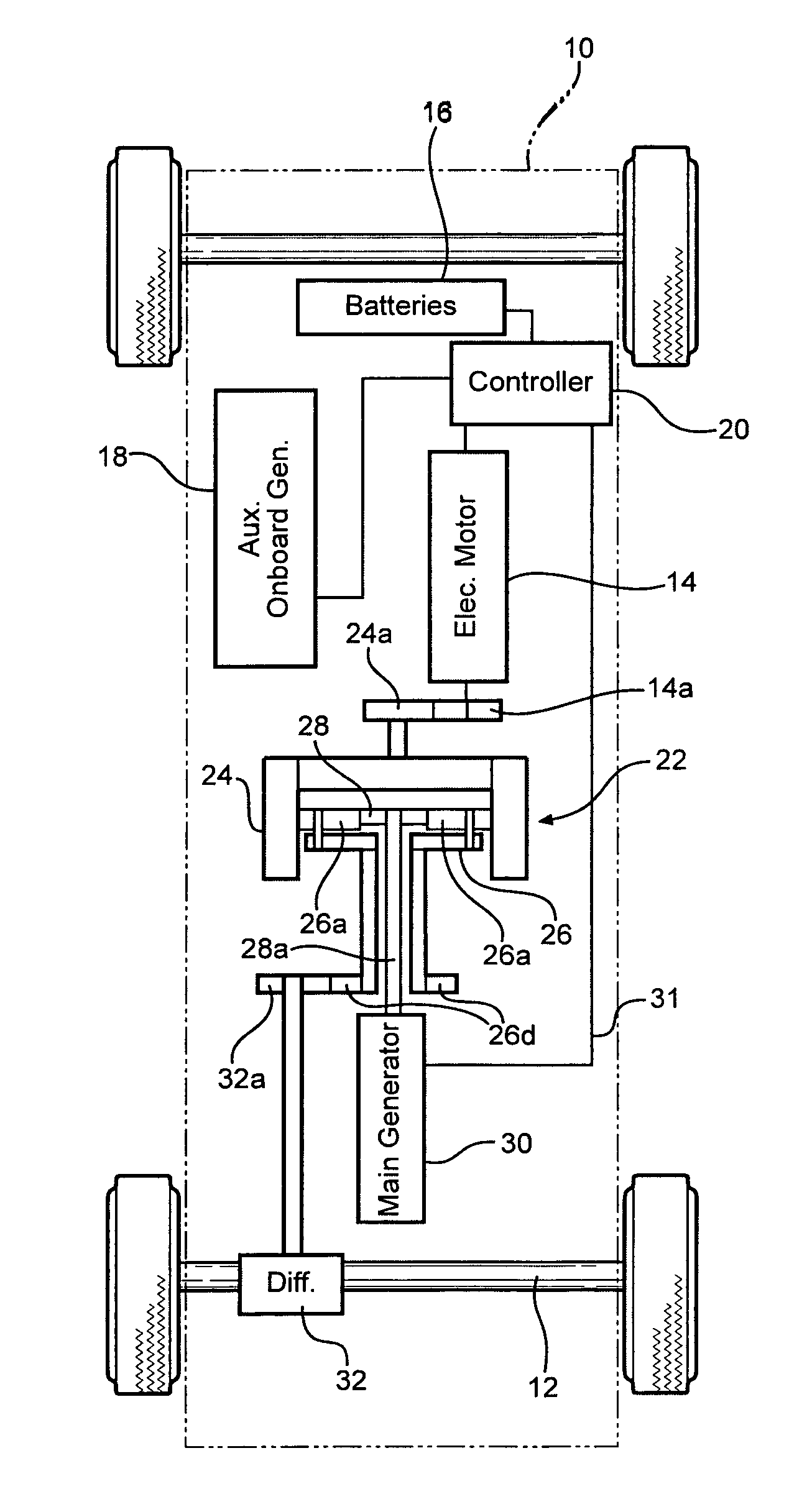
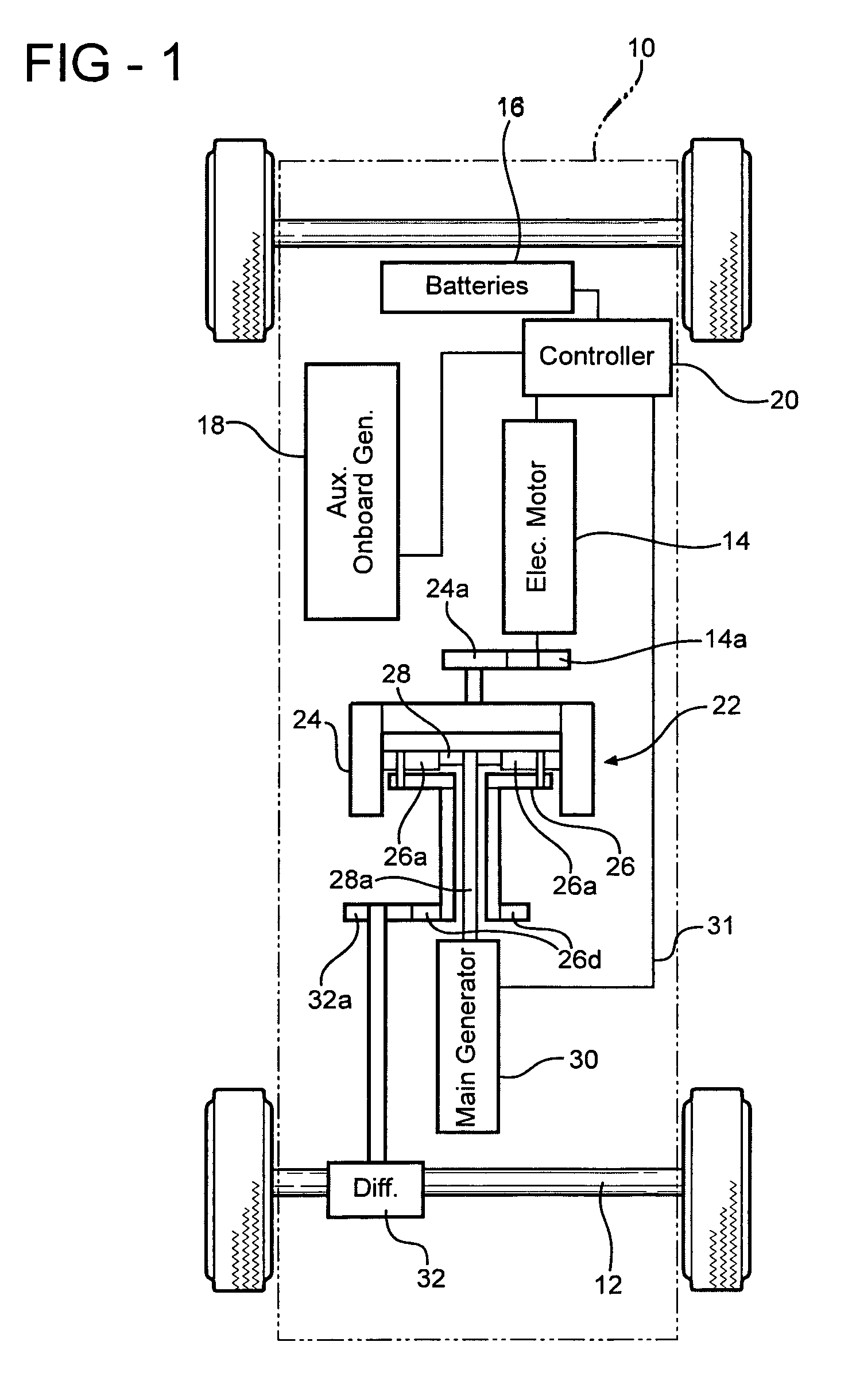
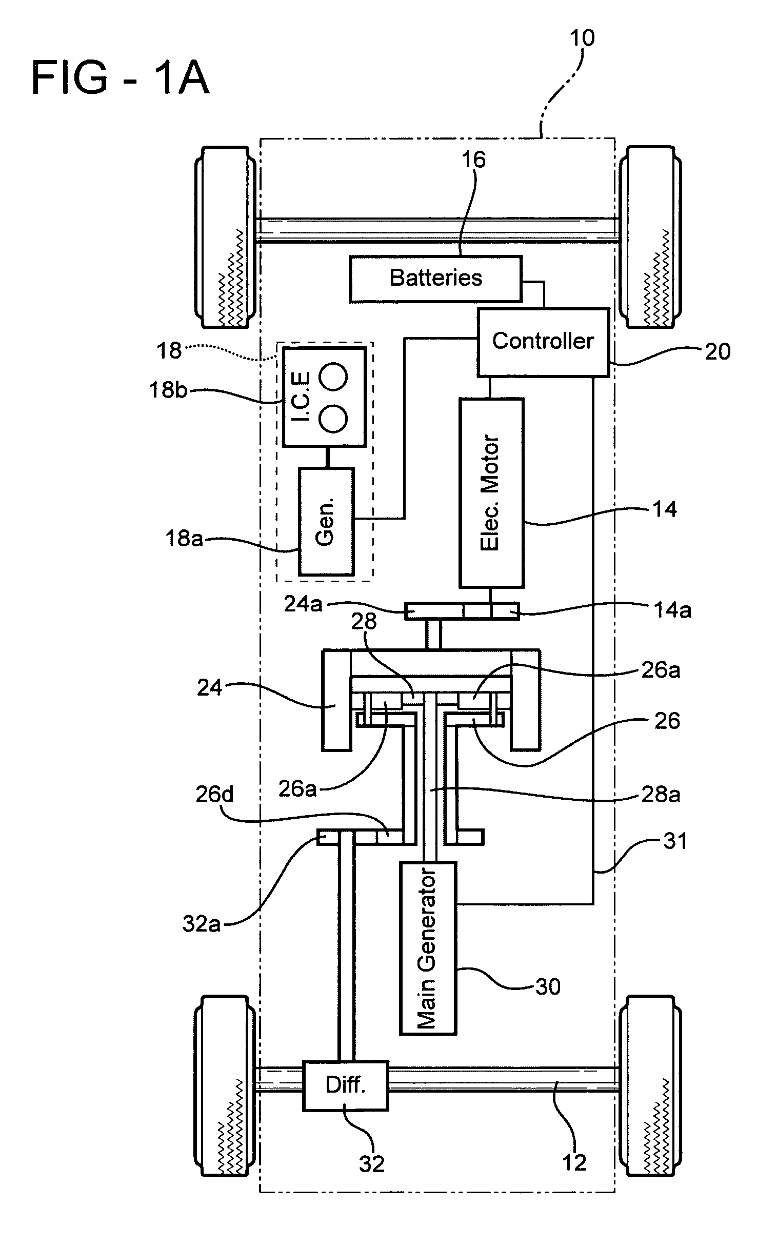
"The invention is an electric vehicle drive that uses a reactive generator mechanism to provide greater torque than typical electric drives. The electric motor requires startup power and more running power than it receives back from the main generator, so additional electrical power is supplied by a battery and / or an auxiliary onboard generator. The main generator is powered by a small and efficient combustion engine. The electric motor drives the main generator through a planetary gear, and the reaction force output of the main generator is used to drive the vehicle drive wheels. The vehicle does not require a clutch. The main generator can also operate as an electric motor to achieve reverse motion of the vehicle. The generator-reactive wheel driving torque produced by the present drive system is believed to be equal to or greater than that of existing electric and hybrid vehicle drive systems, with the advantages of a smaller and more efficient onboard combustion engine, a simpler drive connection to the wheels, reduced battery storage requirements, and lighter weight. The electric drive of the present invention may also be applicable to drive rotary machinery other than vehicle wheels."

Problems solved by technology

Electric vehicles that are driven entirely by an electric motor are relatively slow, low-powered vehicles that typically require large battery banks for even a limited driving range.
These hybrid systems do not generate current unless the combustion engine is operating, and the drive torque from the electric motor is relatively low, so the combustion engine must run much of the time.

Method used


Image

  • Electric vehicle reaction drive
  • Electric vehicle reaction drive
  • Electric vehicle reaction drive

Examples


Embodiment Construction

[0022]Referring first to FIG. 1, the electric reaction drive of the invention is shown in schematic form incorporated into a typical wheeled passenger vehicle 10 having a standard set of front drive wheels 12. In the illustrated embodiment, an electric motor 14 is initially supplied with electric current from batteries 16 and / or an auxiliary onboard generator 18 through a microprocessor or computer type controller 20 that also controls motor function. The torque output of electric motor 14 is connected to drive a planetary gear set 22, with a shaft and / or gear connection 14a to a corresponding shaft and / or gear 24a coupled to rotate the outer ring gear portion 24 of the planetary gear. Ring gear 24 meshes with and rotates planetary gears 26a which are rotatably mounted on the carrier ring assembly 26. Planetary gears 26a mesh with and simultaneously rotate central sun gear 28 coupled via shaft 28a to turn main generator 30. At the same time a drive gear 26d, which is coupled to the ...


PUM


Abstract

An electric drive for a vehicle or other machine having a rotatable drive mechanism, in which the torque output of an electric motor is coupled to drive a main generator through a planetary gear set, the electrical output of the main generator is supplied to the motor to drive the motor, and a reaction torque produced in the planetary gear set from the driving of the generator is coupled to drive the vehicle wheels or other motion means. The reaction torque produced in the planetary gear set in response to the generator torque is greater than the electric motor torque input. Start-up and make-up power for the electric motor are provided by an onboard battery recharged by an auxiliary onboard generator, or by the auxiliary onboard generator.

Description

FIELD OF THE INVENTION[0001]The present invention is in the field of electric and hybrid-electric vehicle drives that provide power in various ways to drive a wheeled vehicle.DESCRIPTION OF THE RELATED ART[0002]Electric vehicles that are driven entirely by an electric motor are relatively slow, low-powered vehicles that typically require large battery banks for even a limited driving range.[0003]Hybrid vehicles that use combustion engines to power and supplement an electric drive motor are currently more practical and are becoming more popular for ordinary passenger vehicles. The typical hybrid drive uses all of the torque output from an electric motor to drive the vehicle's wheels, while a combustion engine adds drive torque to the wheels when the electric motor is not enough, and runs a generator to supply the electricity for the electric motor. These hybrid systems do not generate current unless the combustion engine is operating, and the drive torque from the electric motor is r...

Claims


Application Information

Patent Timeline
Patent Type & Authority Patents(United States)
IPC IPC(8): B60K1/02B60K6/365B60K6/46
CPCB60K6/365B60K6/46F16H3/724Y02T10/6217Y10S903/909Y02T10/62Y02T10/7072
Inventor MEYER, JOHN FRED
Owner MEYER JOHN FRED
Learn More