Multi-beam light source unit, optical scanning device, image formation apparatus, light beam combining unit, optical system, optical apparatus

a light source unit and beam technology, applied in the field of multi-beam light source units, can solve the problems of high cost of laser array light sources, increased difficulty in technology, and increased difficulty in achieving the effect of high layout degree of freedom, inexpensive and compact optical apparatus, and novel characteristics

Inactive Publication Date: 2008-11-11
RICOH KK
View PDF7 Cites 14 Cited by
  • Summary
  • Abstract
  • Description
  • Claims
  • Application Information

AI Technical Summary

Benefits of technology

[0022]A preferred embodiment of the present invention may provide a light beam combining unit having high layout degree of freedom and low manufacturing cost, a multi-beam light source unit, an optical scanning device, an image formation apparatus, an optical system, and an optical apparatus using the light beam combining unit.
[0061]According to the optical apparatus of the present invention, it is possible to realize an inexpensive and compact optical apparatus having novel characteristics.

Problems solved by technology

When the rotational speed is increased, however, noise and heat become a problem.
However, when fabricating a laser array light source, along with an increase of the light emitting spots, such as, 4, 8, . . . , it becomes technically more and more difficult, and this makes the laser array light source very expensive.
This limits the degree of freedom of layout, and may require the multi-beam light source unit to be large sized, and in turn, cause the optical scanning device to be large.
Similarly, this also limits the degree of freedom of layout.
This thin film exhibits high beam splitting performance when being used at specified wavelengths and specified incidence angles, but suffers from the problem in that the beam splitting performance degrades significantly much when the wavelengths and incidence angles deviate from the specified values.

Method used


Image

  • Multi-beam light source unit, optical scanning device, image formation apparatus, light beam combining unit, optical system, optical apparatus
  • Multi-beam light source unit, optical scanning device, image formation apparatus, light beam combining unit, optical system, optical apparatus
  • Multi-beam light source unit, optical scanning device, image formation apparatus, light beam combining unit, optical system, optical apparatus

Examples


first embodiment

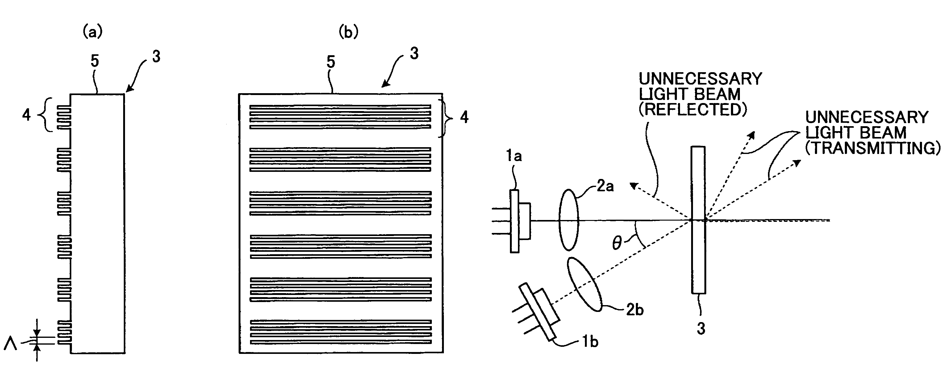
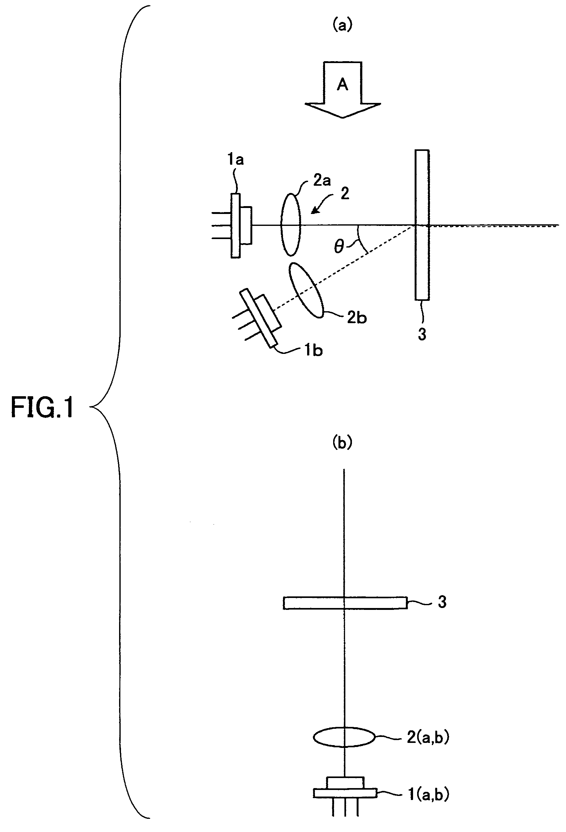
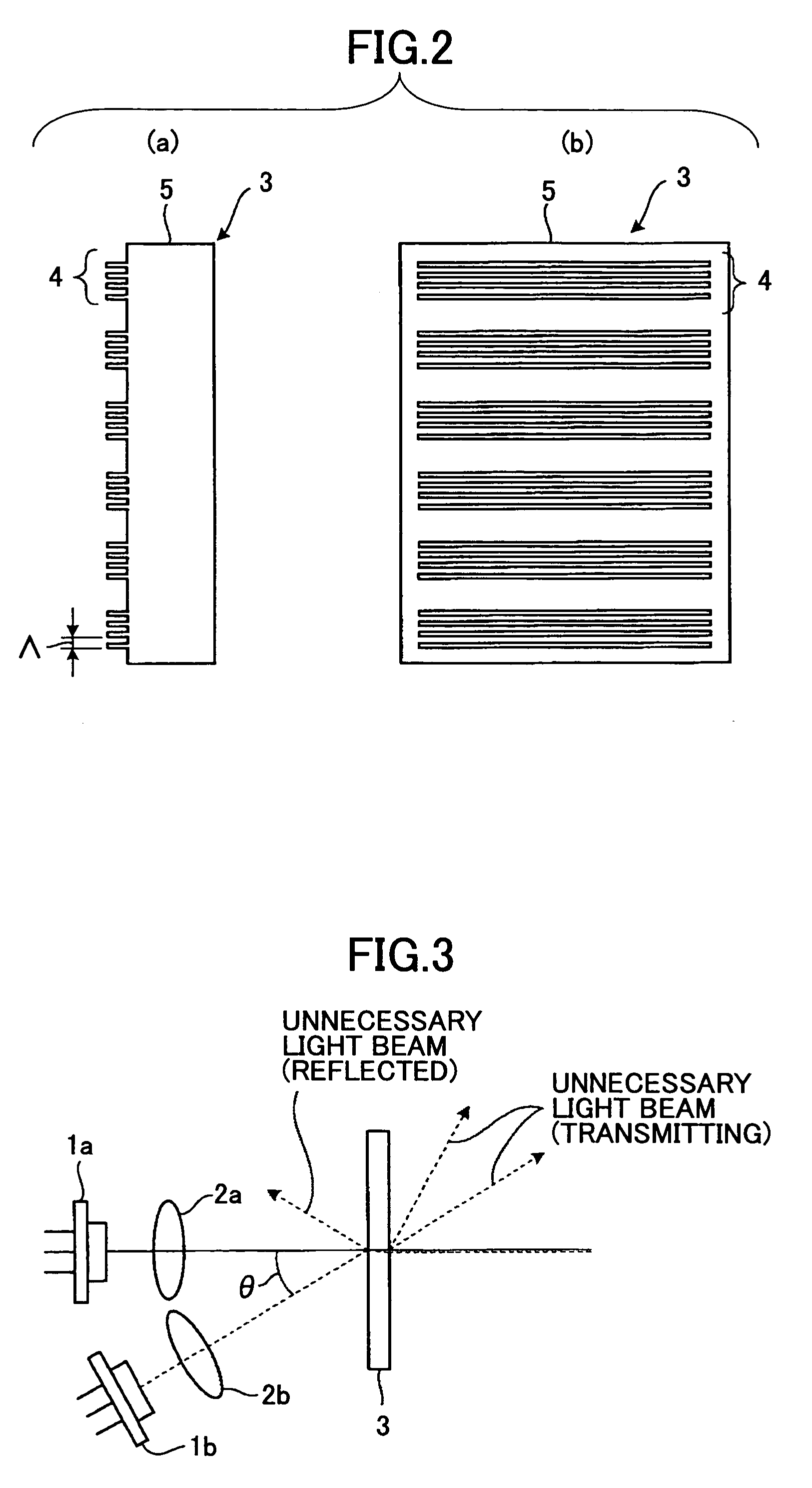
[0094]FIG. 1A and FIG. 1B are schematic views of a multi-beam light source unit according to a first embodiment of the present invention, where, FIG. 1A is a side view and FIG. 1B is a plan view.

[0095]As shown in FIG. 1A and FIG. 1B, the multi-beam light source unit of the present embodiment includes two semiconductor lasers 1a and 1b serving as light sources; a first optical system 2 which condenses the divergent (non-parallel) light beams emitted from the semiconductor lasers 1a and 1b, and converts the divergent light beams into parallel beams, or shapes the divergent light beams emitted from the semiconductor lasers 1a and 1b; and a light beam combining element 3, onto which the two light beams from the first optical system 2 are incident with an angle of θ therebetween.

[0096]As shown in FIG. 1A, the first optical system 2 includes two single-piece lenses 2a and 2b. Certainly, the first optical system 2 may also include mirrors, or plural optical elements.

[0097]The light beam co...

second embodiment

[0128]FIG. 7 is a schematic side view of a multi-beam light source unit according to a second embodiment of the present invention.

[0129]In the present embodiment, the same reference numbers are assigned to the same elements as those shown in the previous embodiment, and overlapping explanations are omitted.

[0130]FIG. 8 is a schematic view of an arrangement of the multi-beam light source unit of the second embodiment allowing polarization directions of two polarized light beams to be different by 90 degrees.

[0131]When the light sources are linearly polarized semiconductor lasers, in order that two incident light beams have polarization states different from each other by 90 degrees as shown in FIG. 4, the semiconductor lasers are arranged so that the polarization directions of the semiconductor lasers are different from each other by 90 degrees.

[0132]FIG. 9 is a schematic view of a portion of a semiconductor laser illustrating light emission of the semiconductor laser.

[0133]As shown ...

third embodiment

[0138]FIG. 10 is a schematic side view of a multi-beam light source unit according to a third embodiment of the present invention.

[0139]The two incident light beams combined by the light beam combining element 3 have polarization directions different from each other by 90 degrees. Hence, in an optical system for guiding the light beams from the multi-beam light source unit, because of the dependence of the light transmittance and reflectivity on the light polarization direction, intensities of the two light beams end up being different after the two light beams are transmitted through the optical system.

[0140]It is preferable that the intensities of the two light beams be different in some applications of the multi-beam light source unit, but in many other applications, it is desirable that the intensities of the two light beams be the same.

[0141]Hence, as shown in FIG. 10, a λ / 4 plate 7 is arranged behind the light beam combining element 3 (downstream along the light propagating di...


PUM


Abstract

A multi-beam light source unit is disclosed that has high layout degree of freedom and low manufacturing cost. The multi-beam light source unit includes two or more light sources, two or more first optical systems that shape light beams from the light sources, and a light beam combining element with a periodic structure of a period shorter than wavelengths of the light beams. The light beams are incident on the light beam combining element from different directions, and the light beam combining element transmits at least portions of the light beams nearly in the same direction.

Description

BACKGROUND OF THE INVENTION[0001]1. Field of the Invention[0002]The present invention relates to a multi-beam light source unit able to scan light beams from plural light sources at the same time and to scan a surface along plural lines, an optical scanning device having the multi-beam light source unit, an image formation apparatus having the optical scanning device, such as a copier, a printer, a facsimile, a plotter or others, a light beam combining unit used in the multi-beam light source unit, an optical system, and an optical apparatus having the light beam combining unit. The light beam combining unit of the present invention is applicable to a combination element used in optical communication.[0003]2. Description of the Related Art[0004]In these years, along with an increase of printing speed of image formation apparatuses, it is desired to improve writing density. For this purpose, in an optical scanning device constituting the image formation apparatus, it is attempted to ...

Claims


Application Information

Patent Timeline
Patent Type & Authority Patents(United States)
IPC IPC(8): G02B26/08
CPCB41J2/473G02B26/123G02B26/124G02B27/283H04N1/1135H04N1/12
Inventor MASUDA, KOJI
Owner RICOH KK
Why Eureka
Try Eureka