Exhaust gas cleaning method and exhaust gas cleaning system

a technology of exhaust gas and cleaning method, which is applied in the direction of machines/engines, electrical control, separation processes, etc., can solve the problems of large amount of pm generated, catalyst cannot burn soot components in the pm by itself, and cannot meet the regulatory value, so as to reduce the richness of the system, reduce the accumulation of pm, and simplify the system

Active Publication Date: 2008-11-18
ISUZU MOTORS LTD
View PDF12 Cites 6 Cited by
  • Summary
  • Abstract
  • Description
  • Claims
  • Application Information

AI Technical Summary

Benefits of technology

[0019]The reduction in the richness described above is performed by reducing a frequency of enrichment by making an interval between the richness controls longer than that between normal richness controls. Alternatively, the reduction in the richness described above is performed through reducing a degree of richness in the following manner. Specifically, the degree of richness is reduced by setting a target oxygen concentration to be relatively low in performing the richness control, thereby reducing an amount of a reducing agent supplied to obtain a high air fuel ratio (A / F) of the exhaust gas and a low excess air ratio (γ). Alternatively, the reduction in the richness is performed by the both described above.
[0032]Therefore, in the engine operating state at such a high load range that the PM is self-ignited, it is possible to perform an optimum richness control capable of suppressing accumulation of the PM while maintaining an optimum NOx purification rate.

Problems solved by technology

The stricter regulations have made it impossible to meet regulatory values only by improving the engine.
Therefore, excessive concentration combustion is performed by changing engine operating conditions, and thereby rich spike gas is generated and supplied to the catalyst.
However, in the case of using the NOx occlusion / reduction type catalyst, the catalyst cannot burn soot components in the PM by itself.
However, since the operating range described above is a high combustion temperature range, a large amount of PM is generated in the rich combustion.
If the PM accumulation amount exceeds its limits, there arises a risk of abnormal combustion and erosion attributable thereto.
Thus, even if the engine operating range is the high load range, it is required to regenerate the DPF by forcibly burning the PM.

Method used


Image

  • Exhaust gas cleaning method and exhaust gas cleaning system
  • Exhaust gas cleaning method and exhaust gas cleaning system
  • Exhaust gas cleaning method and exhaust gas cleaning system

Examples


Embodiment Construction

[0040]With reference to the drawings, an exhaust gas cleaning method and an exhaust gas cleaning system according to embodiments of the present invention will be described below.

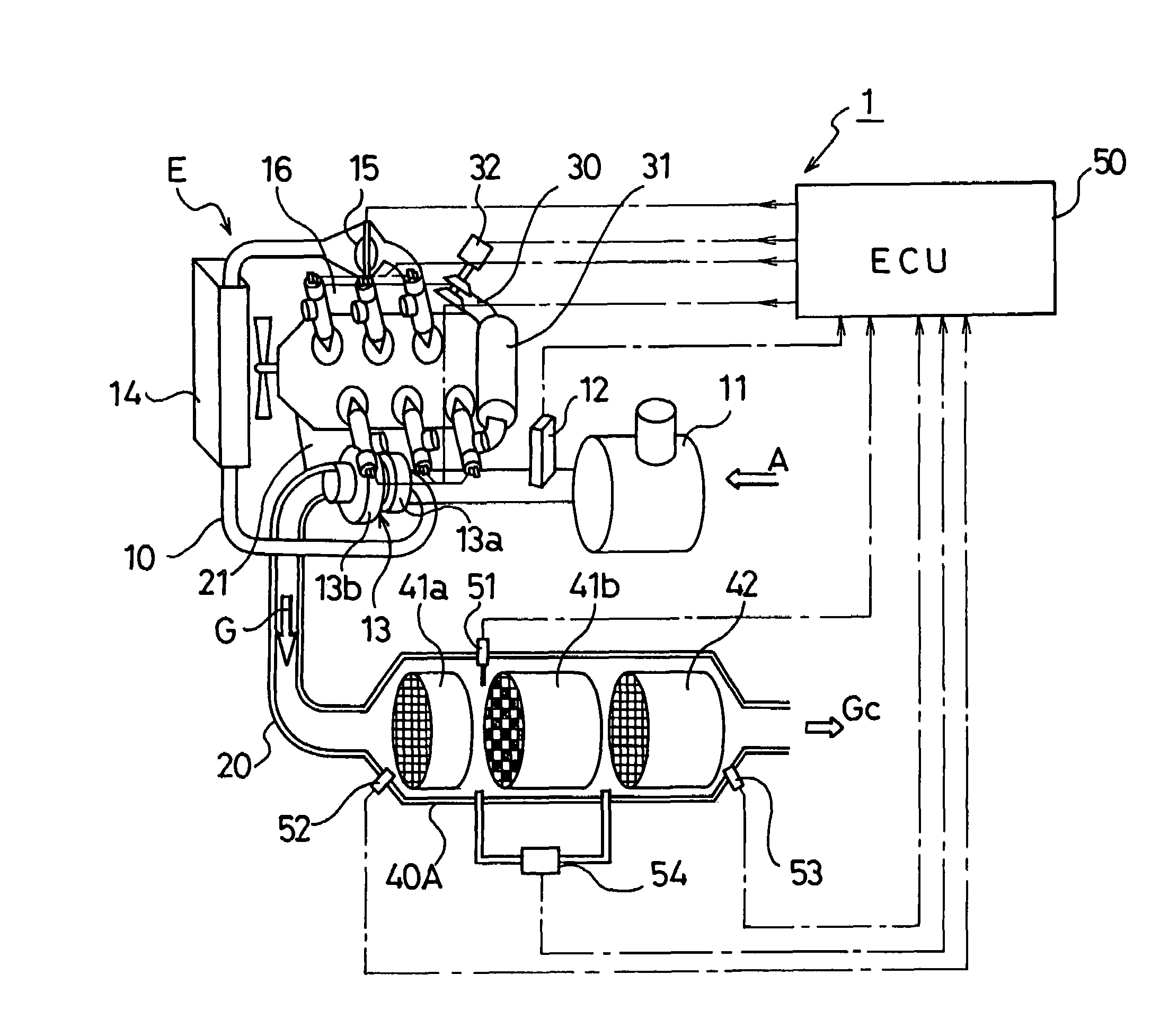
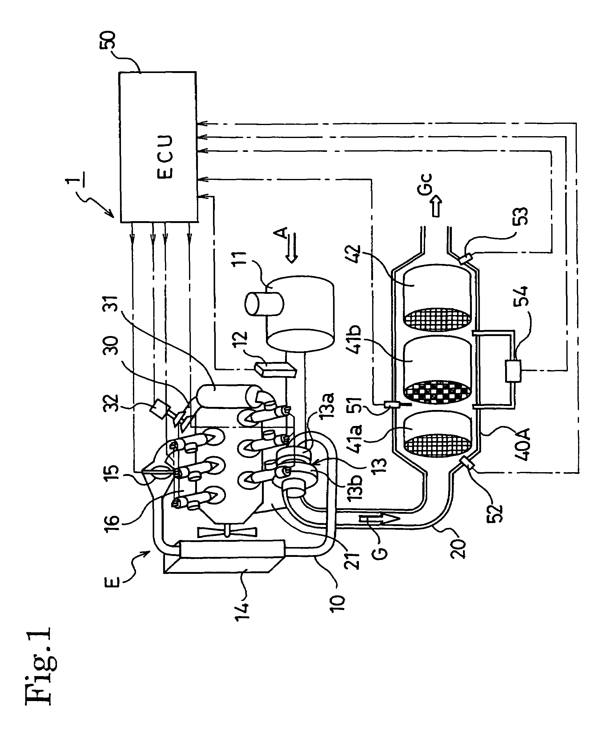
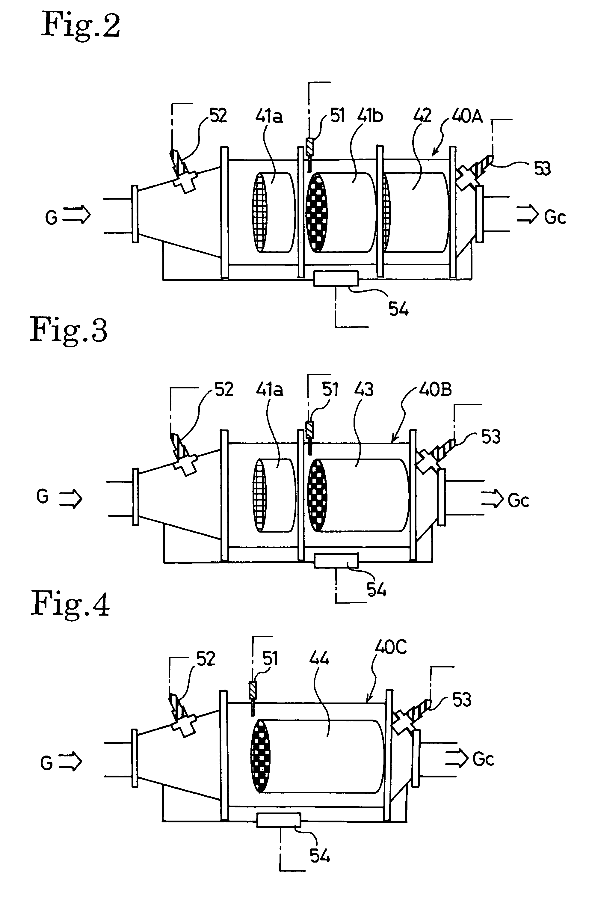
[0041]FIG. 1 shows a configuration of an exhaust gas cleaning system 1 of embodiments. This exhaust gas cleaning system 1 includes an exhaust gas cleaning device 40A in which an oxidation catalyst (DOC) 41a, a DPF 41b and an NOx occlusion / reduction type catalytic converter 42 are sequentially arranged from the upstream in an exhaust passage 20 of an engine (internal combustion engine) E. A continuous regeneration type DPF 41 is formed of the oxidation catalyst 41a located at the upstream side and the DPF 41b located at the downstream side.

[0042]The oxidation catalyst 41a is formed of a monolith catalyst having a number of polygonal cells. The monolith catalyst is a structural material made of cordierite, SiC or stainless steel. On an inner wall of the polygonal cell, a catalyst coat layer is provided, which ...


PUM

PropertyMeasurementUnit
exhaust gas temperatureaaaaaaaaaa
temperatureaaaaaaaaaa

Abstract

An exhaust gas cleaning method capable of maintaining an optimum NOx purification ratio in the continuously regenerative range of DPF in an exhaust gas cleaning system (1) having an NOx purification function and a PM purification function combined with each other and the exhaust gas cleaning system (1). In the exhaust gas cleaning system (1), NOx purification by an NOx occlusion / reduction type catalyst (42) and PM purification by a continuous regeneration type DPF (41) are preformed for exhaust gas from an internal combustion engine. When the temperature (Tent) of the exhaust gas flowing in the DPF (41b) exceeds the self-burning temperature (Tent0) of PM and the differential pressure increasing rate (dP) of a differential pressure across the DPF (41b) exceeds a specified determination value (dP0), at least either of a control to reduce the frequency of enriching the exhaust gas and a control to reduce the degree of richness is performed in a catalyst regenerative control for regenerating the NOx occlusion / reduction type catalyst (42).

Description

[0001]This application is based on and hereby claims priority to PCT Application No. PCT / JP2004 / 008734 flied on Jun. 22, 2004 and Japanese Application No. 2003-178079 filed on Jun. 23, 2003, the contents of which are hereby incorporated by reference.TECHNICAL FIELD[0002]The present invention relates to an exhaust gas cleaning method and an exhaust gas cleaning system for performing NOx purification by an NOx occlusion / reduction type catalyst and PM purification by a continuous regeneration type DPF for exhaust gas from an internal combustion engine such as a diesel engine.BACKGROUND ART[0003]There have been stricter regulations each year on amounts of emissions of NOx (nitrogen oxides) and particulate matter (hereinafter abbreviated as PM) emitted from a diesel engine, along with CO (carbon monoxide), HC (hydrocarbon), and the like. The stricter regulations have made it impossible to meet regulatory values only by improving the engine. Thus, there has been employed a technology of r...

Claims


Application Information

Patent Timeline
Patent Type & Authority Patents(United States)
IPC IPC(8): F01N3/00B01D46/42F01N3/02B01D53/86B01D53/94F01N3/023F01N3/025F01N3/029F01N3/035F01N3/08F01N3/18F01N3/20F01N3/24F01N3/28F01N13/02F02B29/04F02B37/00F02D41/02F02D41/04F02M25/07
CPCB01D53/9431F01N13/0097F01N3/035F01N3/0814F01N3/0821F01N3/0842F02D41/0275F02D41/029F02M25/0754B01D53/9495F02B29/0425F02B37/00F02D41/1446F02D2200/0812F02M25/0707F02M25/0727F02M26/05F02M26/23F02M26/47
Inventor NAGAOKA, DAIJIGABE, MASASHISAKAMOTO, TAKAYUKI
Owner ISUZU MOTORS LTD
Why Eureka
Try Eureka