
Nanoindentation surface analysis tool and method

a surface analysis and nanoscale technology, applied in the field of nanoscale surface analysis, can solve the problems of bulk property analysis, inability of most mechanical characterization instruments and methods to evaluate the real surface of a material, destructive mechanical analysis, etc., and achieve the effect of fast sample throughpu

Inactive Publication Date: 2008-11-18
IBM CORP
View PDF7 Cites 18 Cited by
  • Summary
  • Abstract
  • Description
  • Claims
  • Application Information

AI Technical Summary

Benefits of technology

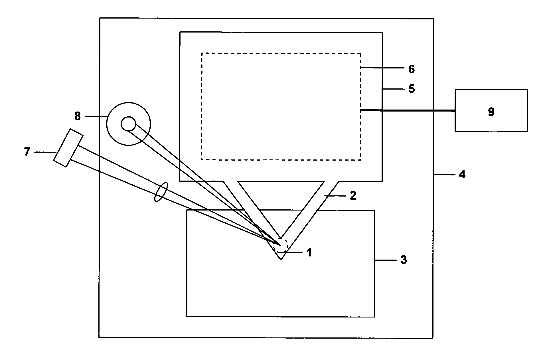
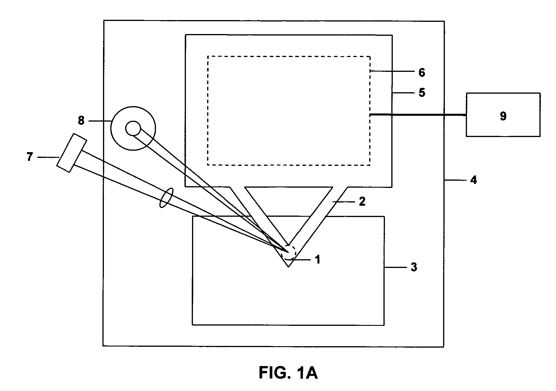
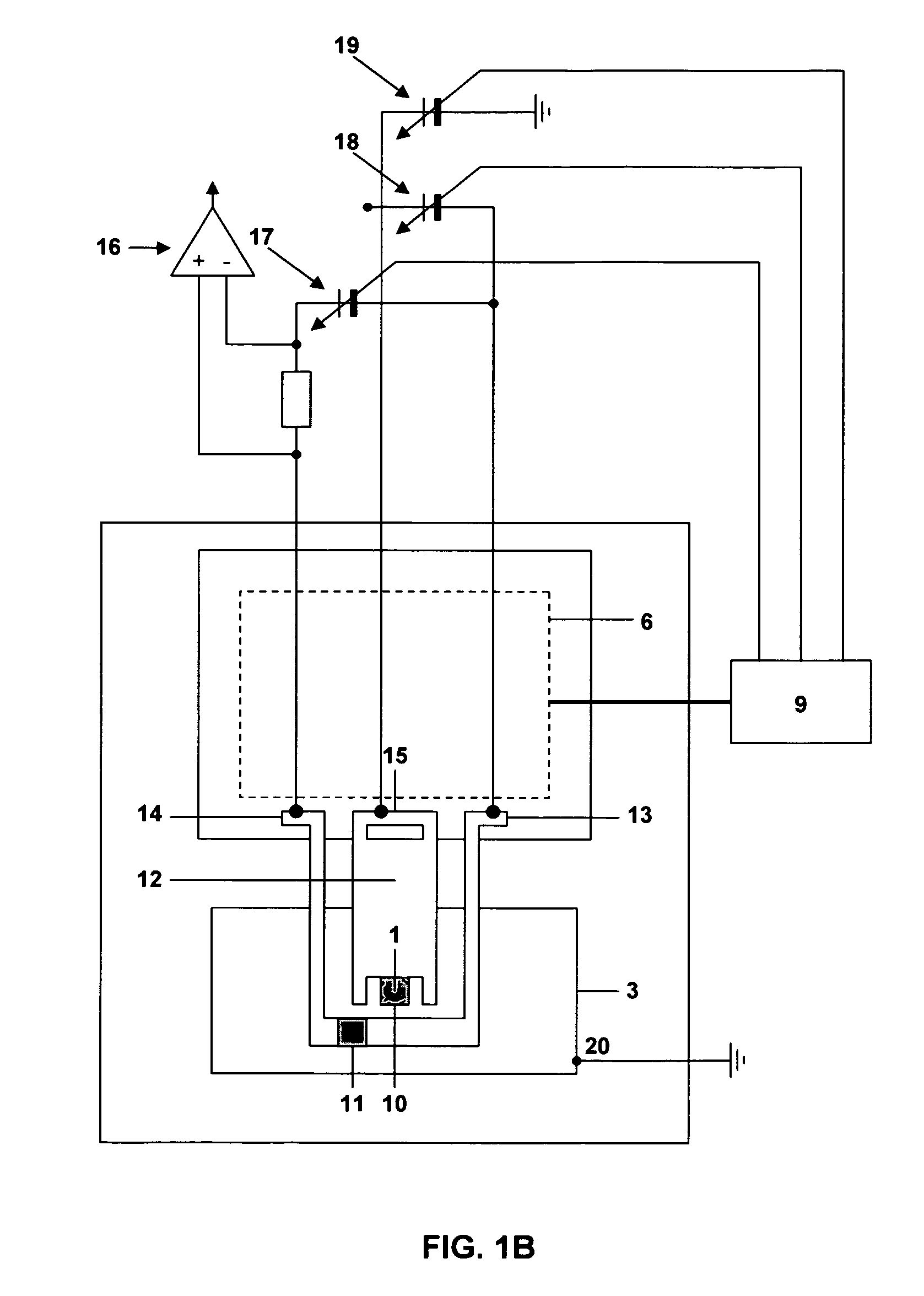
The present invention provides a method for measuring the mechanical properties of a surface as a function of temperature, load, and time using a nanoindentation surface analysis tool. The tool consists of a heatable cantilever tip and a microfabricated tip. The method involves positioning the tip relative to the surface, contacting it with the surface, heating the tip, applying a load to the tip, and determining the depth of indentation. The method can be performed using a single tip or an array of tips. The resolution of the measurement depends on the number of indents. The invention allows for faster and more cost-effective measurement of hardness and glass transition temperature.

Problems solved by technology

Currently, mechanical analysis is destructive and a bulk property analysis.
Most mechanical characterization instruments and methods are unable to evaluate real surface of a material, but instead look at a shallow but still bulk response for the film or material.
Typically, hardness as a function of temperature, especially relative to glass transition temperature (Tg) of the surface of the material or thin film is not directly or efficiently measured.
As a result of the high stress acting on the indenter tip the latter wears rapidly resulting in a blunted apex after only a few indentation experiments.
Hence, tip-wear is a serious issue in such investigations.
While AFM, as well as, other currently existing techniques can be used to analyze the mechanical properties of the majority of thin films there are distinct disadvantages associated with these techniques which limit their general applicability.
In particular, many current methods are lacking in their ability to provide information on Tg and hardness for many thin films for a number of reasons.
First, in some instances the material can only be made in thin film form without sacrificing essential properties.
Most current techniques however, require more material than a mere film.
Thus, often the film is too thin for conventional hardness testing.
With respect to glass transition temperature (Tg) the film is often not thick enough to allow the application of bulk averaging techniques such as Differential Scanning Calorimetry (DSC) or Dynamic Mechanical Thermal Analysis (DMTA), etc; or the film is made on a sample substrate which itself degrades thermally or interferes otherwise with the measurement.
In particular, the sample may not be heatable to sufficiently high temperatures; and other, non-averaging techniques for surface characterization (such as AFM friction measurements) are often too tedious.
Finally, occasionally the material may only be made as one of several phases of a compound for which techniques for the measurement of Tg and hardness are not yet available.
Published methods are often not sufficiently reliable and their application is typically too tedious to be of practical use.

Method used


Image

  • Nanoindentation surface analysis tool and method
  • Nanoindentation surface analysis tool and method
  • Nanoindentation surface analysis tool and method

Examples


example 1

General Method for Surface Analysis

[0105]An array of cantilever tips comprised of conductive, hard and stable materials such as silicone, silicone nitride or carbon are placed above the surface to be analyzed so as not to be in contact at the beginning of the scan. Smooth surfaces (<5 nm Ra) are preferable, but rough surface can also be characterized using this technique, but with less precision for the hardness measurements and a decreased probe tip lifetime. A coarse scan is optionally made over a wide range of temperature (20° C. to 600° C. using a coarse sampling rate ˜1 sample / 50° C.) and a wide range of load (10 nN to several μN using a coarse sampling rate of 1 sample per 100 nN). In other embodiments even coarser scans can be made if desirable. To perform the scan either the probe tip array or the sample can be moved. In preferred embodiments, the array is fixed and a precision sample stage is employed to move the sample under the fixed tip array. Using the results obtained ...

example 2

Specific Methods for Measurement of Tg and Hardness of a Thin Film

[0107]This example describes three different protocols for measurement of Tg and hardness.

Method (I)

[0108]According to Method (I) the temperature dependent hardness (T(F)) was measured at one indentation depth (see e.g. FIG. 4 in which an indentation depth of 0.5 nm was used). The function T(F) is a measure of the temperature dependent hardness. The room temperature hardness, as commonly cited in literature, was obtained by extrapolation to T=room temperature as illustrated in FIG. 5 (●). Extrapolation of T(F) to zero load (F=0) provides a measure of the local glass transition temperature as shown in FIG. 6. It should be noted that the conversion factor relating Tg to T_heater in FIG. 6 depends on the tip shape. The shape of the tip can easily be determined by SEM or by using a reference measurement on a known sample. The same applies to the conversion factor between F(T=0) and the hardness.

Method (II)

[0109]Method (II...


PUM

PropertyMeasurementUnit
temperatureaaaaaaaaaa
thickaaaaaaaaaa

Abstract

The present invention provides a novel method for determining the mechanical properties of the surfaces of materials including thin films. Generally, the method is comprised of laterally scanning the surface of the film with an array of cantilever tips varying temperature, load and time to obtain a measurement of mechanical properties, such as hardness and glass transition temperature. The method can be used to obtain mechanical properties of films that would otherwise be unobtainable using standard methods.

Description

TECHNICAL FIELD[0001]The present invention relates generally to the field of nanoscale surface analysis. More specifically, the present invention relates to a novel method for the measurement of the mechanical properties of the surfaces of materials and thin films.BACKGROUND ART[0002]One of the most important material configurations in the field of microelectronics, thin film technology and surface coatings technology consists of a polymeric coating material deposited as a thin film onto a substrate of another material. The proper selection of polymeric materials and their on-going inspection for process control often requires very precise knowledge of the mechanical properties. Currently, mechanical analysis is destructive and a bulk property analysis. For many parts, coatings and thin films made from plastics, the bulk properties are not the crucial property which needs to be monitored or controlled. It is the mechanical properties of the surface of the coating or molded material ...

Claims


Application Information

Patent Timeline
Patent Type & Authority Patents(United States)
IPC IPC(8): G01N3/32
CPCB82Y35/00G01Q60/366G01Q70/06G01Q60/58
Inventor BRADSHAW, RICHARD L.DUERIG, URS T.GOTSMANN, BERND W.
Owner IBM CORP
Learn More