Flexible tube

a flexible tube technology, applied in the field of flexible tubes, can solve the problems of increasing exhaust noise, affecting the performance of the engine, easy leakage of high-temperature exhaust gas, etc., and achieve the effects of reducing the loss of flow, suppressing the turbulence of exhaust gas, and improving the flow efficiency

Inactive Publication Date: 2008-11-18
HIROTEC CORP
View PDF18 Cites 24 Cited by
  • Summary
  • Abstract
  • Description
  • Claims
  • Application Information

AI Technical Summary

Benefits of technology

[0014]According to the first aspect of the invention , by providing a gap as a buffering space between bottoms of the pleats of the outer bellows and tops of the pleats of the inner bellows, the amounts of exhaust noise and heat released from the inner bellows are suppressed by the buffering space, thus durability of the outer bellows is improved, and the amounts of exhaust sound and heat released from the outer bellows can be reduced. In addition, in a case of a flexible tube disposed upstream of the catalytic converter, the lowering of the temperature of the exhaust gas to be fed into the catalytic converter is suppressed, leading to quick temperature rise of the exhaust gas to be fed into the catalytic converter, thus resulting in improved capability to purify exhaust gas.
[0049]According to the eighteenth aspect of the invention, instead of by providing a bellows in the form of a plate, by providing the flexible part including two steel plates having spring property, one end part thereof being fixed to the partition on the inlet side in such a manner that the partition is clamped by the two steel plates, and the other end part thereof holding the partition on the outlet side in such a manner that the partition is clamped by the two steel plates, expensive bellows is not necessary, and an inexpensive flexible part can be introduced easily. Moreover, as compared with the flexible tube having a flexible part with bellows, turbulence in the exhaust gas is suppressed and the loss of the flow is reduced, leading to the improvement in the flow efficiency and thus in the output of the engine.

Problems solved by technology

However, this fiber cloth has a problem in that high-temperature exhaust gas easily leaks out through space left between the fibers and reaches the outer bellows, having harmful effects on durability, spring property and the like of the outer bellows.
In addition, exhaust sound also passes through space left between the fibers, reaches the outer bellows, and then leaks out from the flexible tube 80, thus increasing exhaust noise.
Therefore, during the initial period of engine start-up, the temperature of the exhaust gas becomes lower and the temperature rise of the exhaust gas to be fed into the catalytic converter C takes longer, resulting in poor performance capability to purify the exhaust gas.

Method used


Image

  • Flexible tube
  • Flexible tube
  • Flexible tube

Examples


first embodiment

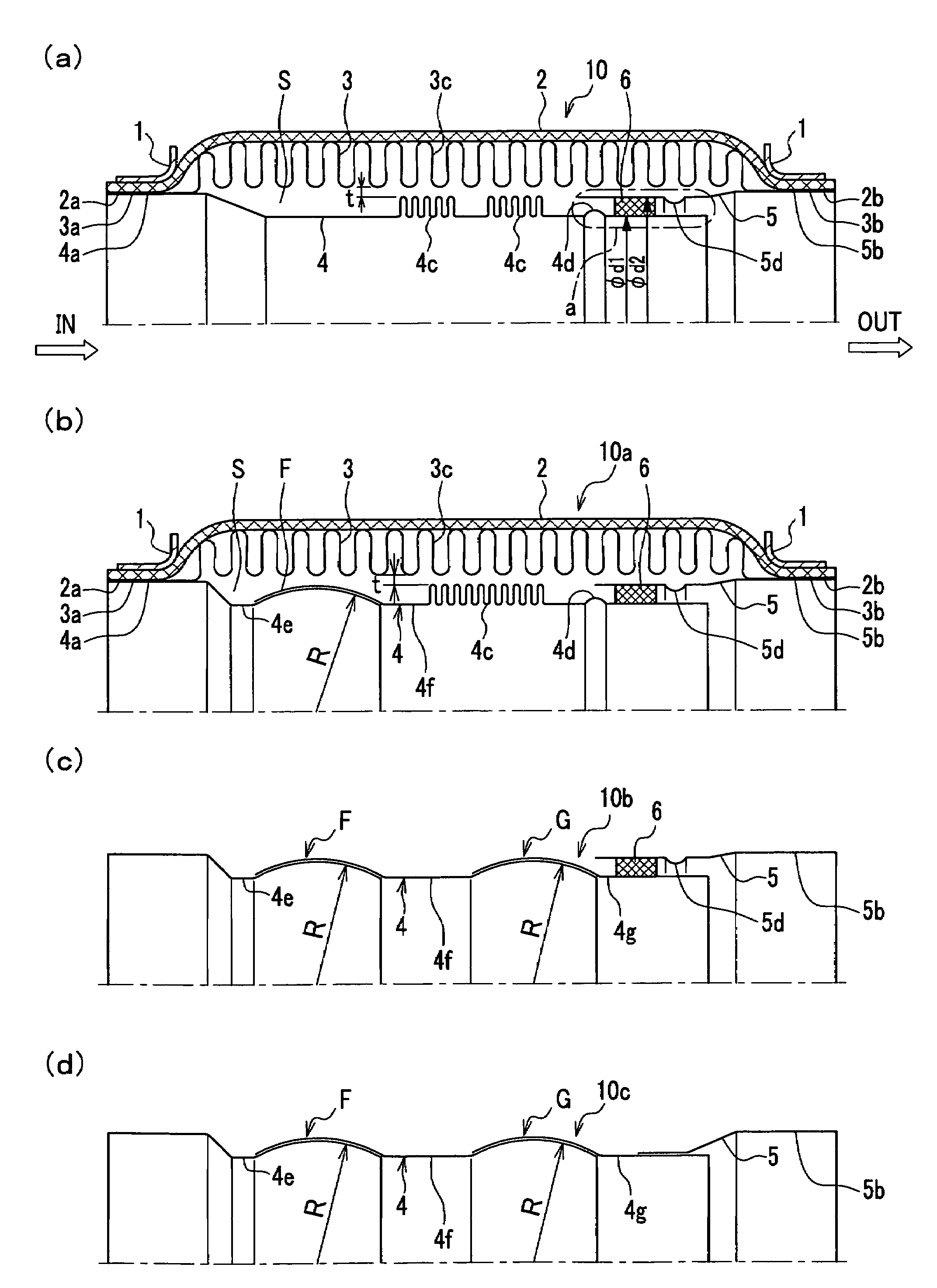
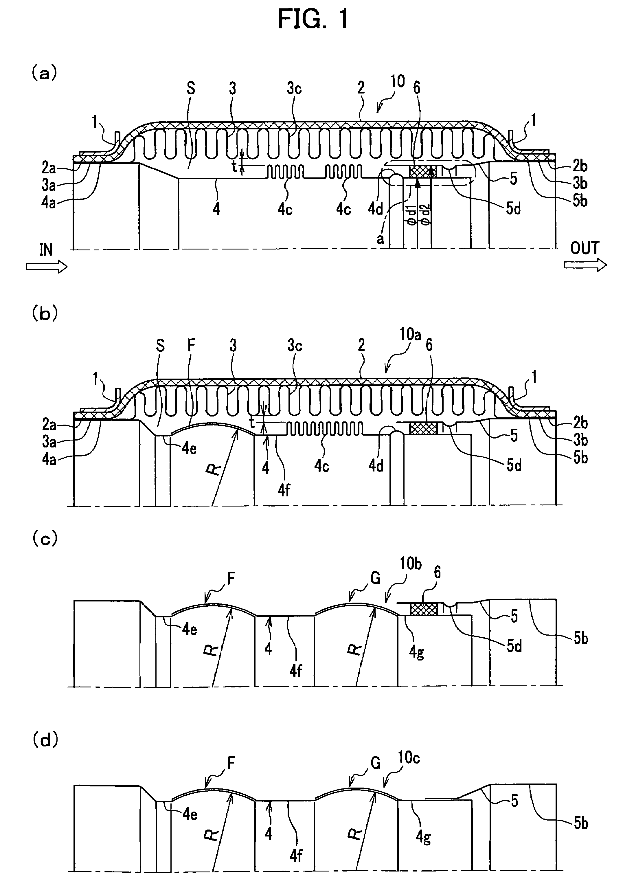
[0060]FIG. 1(a) shows a half sectional view of a flexible tube according to a first embodiment of the present invention. As shown in FIG. 1(a), the flexible tube 10 includes protectors 1,1, an outer blade 2, an outer bellows 3, an inner bellows 4, an auxiliary pipe 5 and an interference prevention member 6. A buffering space S is provided with a gap t between the pleats bottoms (inner diameter) of the outer bellows and the pleats tops (outer diameter) of the inner bellows. The flexible tube 10 has, for example, a diameter of φ90 mm at the thickest portion and the overall length of approximately 200 mm.

[0061]The protectors 1 are provided on both end parts of the flexible tube 10. The cross section of the protector 1 is nearly L-shaped. On the inner periphery of the protector 1, the end part of the outer blade 2 is fixedly installed, in such a manner that the elevation part of the outer blade 2 is protected.

[0062]The outer blade 2 is formed of thread of SUS 304 alternately woven, and ...

second embodiment

[0075]FIG. 1(b) shows a half sectional view of a flexible tube according to a second embodiment of the present invention. As shown in FIG. 1(b), a flexible tube 10a includes protectors 1,1, an outer blade 2, an outer bellows 3, an inner bellows 4, an auxiliary pipe 5 and an interference prevention member 6. The inner bellows 4 is separated into two pieces, inner bellows 4e and 4f.

[0076]On the right end part of the inner bellows 4e, a spherical surface is provided whose convex outer periphery having a radius R with its center aligned on the axis of the inner bellows can rotatably slide (hereinbelow, this spherical surface is referred to as “outer spherical surface”). On the left end part of the inner bellows 4f, a spherical surface is provided whose convex inner periphery having a radius R with its center aligned on the axis of the inner bellows can rotatably slide (hereinbelow, this spherical surface is referred to as “inner spherical surface”). The outer spherical surface and the ...

third embodiment

[0080]FIG. 1(c) shows a half sectional view of a flexible tube 10b according to a third embodiment of the present invention. In FIG. 1(c), the protectors 1,1, the outer blade 2 and the outer bellows 3 are omitted, but in practice, the tube has a structure similar to that shown in FIG. 1(b). In this third embodiment, another spherical joint G is provided, in addition to the above-mentioned spherical joint F shown in FIG. 1(b). Here, the spherical joint G is explained.

[0081]The inner bellows 4 is separated into three pieces, inner bellows 4e, 4f and 4g. Referring to the spherical joint G, an outer spherical surface (male form) is provided on the right end part of the inner bellows 4f, and the inner spherical surface (female form) is provided on the left end part of the inner bellows 4g. In addition, the outer spherical surface and the inner spherical surface engage and pivotally support each other to provide a spherical joint G that can rotatably slide. Other components, which are the...


PUM


Abstract

A flexible tube 10 of the present invention is disposed downstream of a exhaust path from an engine E, and formed of an outer bellows 3 as an outer tube and an inner bellows 4 as an inner tube; pleats 4c,4c of the inner bellows 4 are smaller in depth and pitch than the pleats 3c of the outer bellows 3, and the buffering space S is provided with a gap t between the pleats bottoms of the outer bellows 3 and the pleats tops of the inner bellows 4, and further, a partition 17 that splits the exhaust path is disposed in the inner bellows 4. For this reason, sound insulation effect is improved, and the lowering of the temperature of the exhaust gas is suppressed, leading to quick temperature rise of the exhaust gas to be fed into the catalytic converter, thereby promoting the activation of the catalysts and improving the capability to purify exhaust gas, and the exhaust efficiency can be improved thereby increasing output performance of the engine.

Description

TECHNICAL FIELD[0001]The present invention relates to a flexible tube to be provided in an exhaust system for an engine.BACKGROUND ART[0002]An exhaust system for releasing exhaust gas from an automobile engine to the outside environment is explained below. FIG. 8(a) shows a cutaway perspective view of an exhaust system connected to an engine of a conventional or existing automobile.[0003]As shown in FIG. 8(a), an exhaust system A includes: an exhaust manifold M1 for collecting exhaust gas from cylinders of an engine E; a flexible tube P1 connected to the exhaust manifold M1; a catalytic converter C for purifying toxic components in the exhaust gas by oxidation with catalysts; a center pipe P2; a muffler M3 for attenuating the throbbing of the engine E utilizing the principles of sequential expansion of the exhaust gas, resonance, interference and absorbance of sonic waves, cooling of the gas and the like; and a tail pipe P3. Depending on types of automobiles, a sub muffler M2 (not s...

Claims


Application Information

Patent Timeline
Patent Type & Authority Patents(United States)
IPC IPC(8): F16L11/00F16L27/00F01N13/08F01N13/02F01N13/14F01N13/18F16L27/12
CPCF01N13/14F01N13/1816F01N13/009Y10S285/903F01N2230/04F16L27/1004F16L27/111F01N13/08
Inventor TAIRA, MASAOKUMASAKI, MICHISADA
Owner HIROTEC CORP
Why Eureka
Try Eureka