
Diffusion system

a diffusion system and diffusion tube technology, applied in the direction of solid-state diffusion coating, crystal growth process, coating, etc., can solve the problems that the conventional diffusion system lacks high frequency response and robust characteristics against external disturbance, and the conventional diffusion system cannot systemically meet the foregoing requirements, so as to prevent a sag in the exhausting tube

Inactive Publication Date: 2008-11-18
SAMSUNG ELECTRONICS CO LTD
View PDF18 Cites 8 Cited by
  • Summary
  • Abstract
  • Description
  • Claims
  • Application Information

AI Technical Summary

Benefits of technology

[0008]The present invention provides a diffusion system which uniformizes the concentration of a gas mixture in a short amount of time, effectively controls the speed with which a wafer that has undergone a diffusion process is cooled, and stably exhausts a waste gas.
[0013]A portion of the premixer container, which exhausts the gas mixture to the gas mixture supply tube, may have a tapering or conic shape to prevent a whirl in corners of the premixer container.
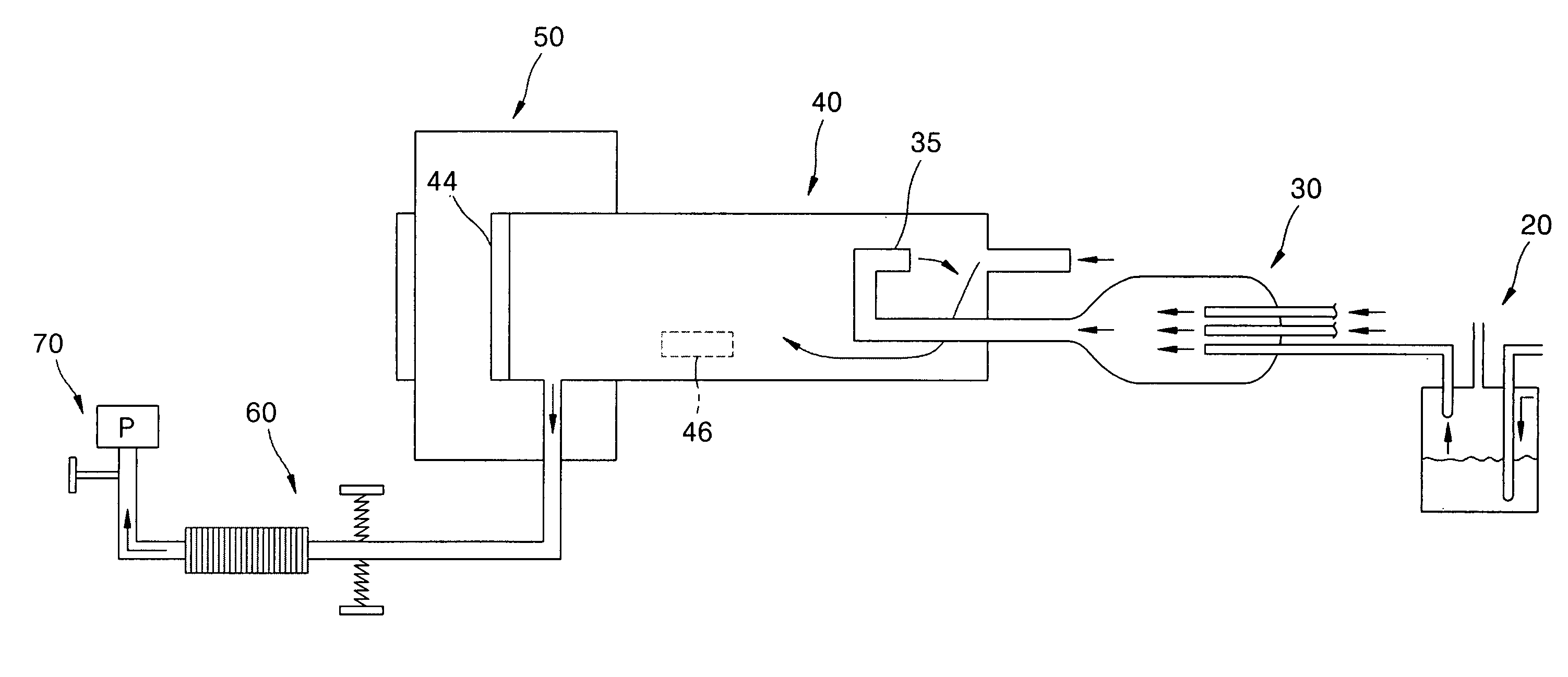
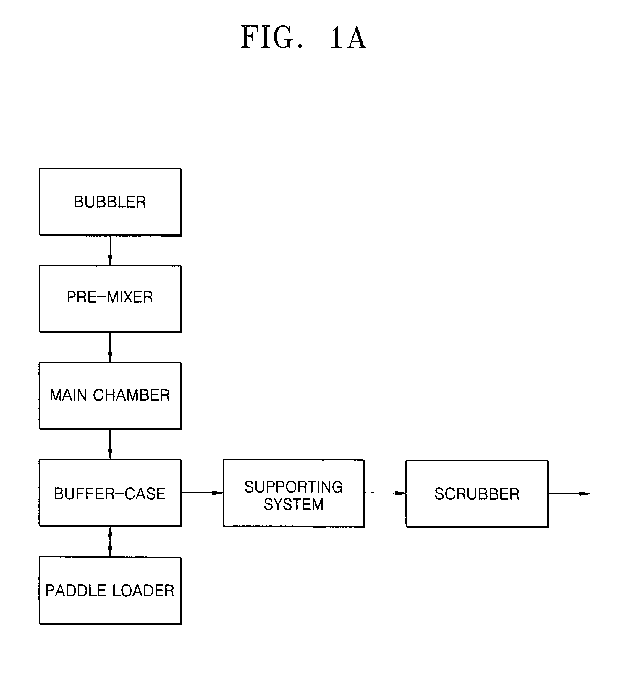
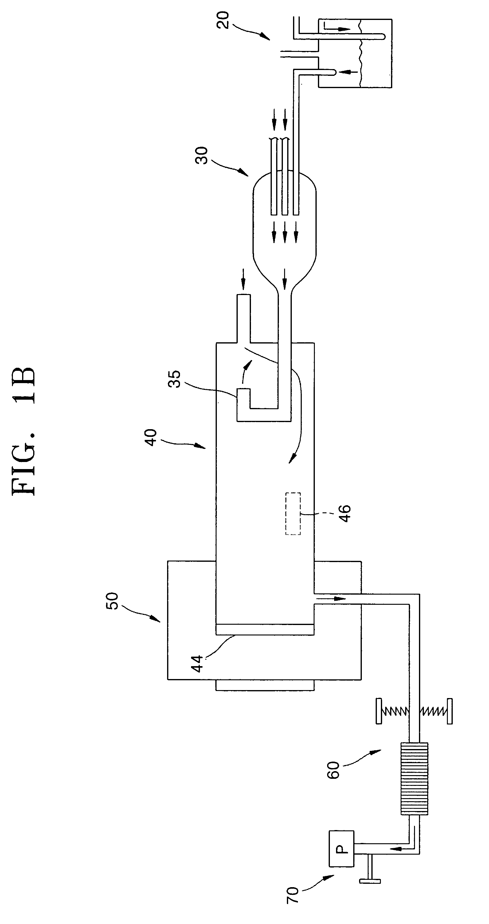
[0020]The waste gas exhausting system may include a supporting system that prevents a sag in the exhausting tube due to the high-temperature waste gas; and a scrubber that finally exhausts the waste gas.
[0021]The supporting system may include a spring that supports the exhausting tube in a radial direction to prevent a sag in the exhausting tube due to thermal expansion; and a bellows that corrects thermal expansion of the exhausting tube in an axial direction and cools the waste gas with an increased surface area.
[0022]According to another aspect of the present invention, there is provided a premixer for supplying a gas mixture containing a doping gas to a main chamber in which the gas mixture reacts to a wafer. The premixer includes a premixer container; one or more gas carrier tubes that receive the doping gas and reactive gases; a gas mixture supply tube that supplies the gas mixture from the premixer container to the main chamber; and a premixer heater that controls the temperature of the premixer.
[0024]According to further another aspect of the present invention, there is provided a waste gas exhausting system for exhausting a remaining waste gas from a main chamber after a wafer reacts to gases. The waste gas exhausting system comprises an exhausting tube, through which the waste gas flows to an exhaust port of the main chamber; a supporting system that prevents a sag in the exhausting tube due to the high-temperature waste gas and cooling the waste gas; and a scrubber finally that exhausts the waste gas using a vacuum pump connected to a terminal portion of the scrubber.

Problems solved by technology

A conventional diffusion system lacks high frequency response and robust characteristics against external disturbances, which are required to form an ultrathin doping layer with a thickness of 100 nm or less, namely, a doping layer for diffusing thermal energy.
However, the conventional diffusion system cannot systemically fulfill the foregoing requirements.

Method used


Image

  • Diffusion system
  • Diffusion system
  • Diffusion system

Examples


Embodiment Construction

[0038]The present invention will now be described more fully with reference to the accompanying drawings, in which exemplary embodiments of the invention are shown. It should be understood that the drawings are exaggerated for clarity of explanation.

[0039]Referring to FIGS. 1A and 1B, a diffusion system according to the present invention includes a diffusion preprocessing portion, a main chamber 40, and a diffusion postprocessing portion.

[0040]The diffusion preprocessing portion includes a bubbler 20, a premixer 30, and a back nozzle 35. The bubbler 20 generates a doping gas, and the premixer 30 premixes the generated doping gas at an appropriate temperature and preheats the same. The back nozzle 35 uniformly mixes the preheated gas with an atmospheric gas in the main chamber 40. Inside the main chamber 40, the doping gas is uniformly mixed with the atmospheric gas and reacts to a wafer, which is loaded in or unloaded from the main chamber 40 via a door 46 included in the main chamb...


PUM

PropertyMeasurementUnit
thicknessaaaaaaaaaa
temperatureaaaaaaaaaa

Abstract

Provided is a diffusion system for forming a doping layer in a wafer. The diffusion system includes a bubbler for generating a doping gas; a premixer, which premixes the doping gas with reactive gases and preheats the gas mixture; a main chamber, in which the gas mixture reacts to the wafer; a buffer case, which externally isolates an exhaust port and a door for loading and unloading the wafer into and out or the main chamber; and a used gas exhaustion system, which exhausts a used gas after the reaction is finished in the main chamber.

Description

[0001]This application claims the priority of Korean Patent Application No. 2003-75814, filed on Oct. 29, 2003, in the Korean Intellectual Property Office, the disclosure of which is incorporated herein in its entirety by reference.BACKGROUND OF THE INVENTION[0002]1. Field of the Invention[0003]The present invention relates to a diffusion system, and more particularly, to a diffusion system for forming an ultrathin doping layer in a wafer. The diffusion system uniformizes the concentration of a mixed gas for forming the doping layer in a short amount of time, includes a cooling rate controller for securing a high frequency response, and provides a flow system for allowing a stable gas flow.[0004]2. Description of the Related Art[0005]A material doped into a semiconductor device is selected in consideration of a diffusion coefficient, a solid-solubility characteristic, a mask effect of an oxide layer, and the like. Even if combined atoms are separated from a doping material during a ...

Claims


Application Information

Patent Timeline
Patent Type & Authority Patents(United States)
IPC IPC(8): C23C16/448C23C16/455C23F1/00C23C16/22H01L21/223C23C8/06C23C16/44C23C16/452C23C16/54C30B31/06C30B31/10C30B31/16C30B35/00H01L21/22
CPCC23C8/06C30B31/06C30B31/10C30B31/165C30B35/00
Inventor KIM, JUN-YOUNGCHOI, BYOUNG-LYONGLEE, EUN-KYUNG
Owner SAMSUNG ELECTRONICS CO LTD
Learn More