Powder particle disintegrating and sizing apparatus

a technology of sizing apparatus and particle, which is applied in the direction of cocoa, strainers, solid separation, etc., can solve the problems of contaminating product particles, clogging of the screen mesh with processed materials, and wear and break down of screens

Inactive Publication Date: 2008-11-25
NARA MACHINERY
View PDF10 Cites 4 Cited by
  • Summary
  • Abstract
  • Description
  • Claims
  • Application Information

AI Technical Summary

Benefits of technology

[0014]Crushing and sizing are carried out specifically by the peripheral edges of the circular plates, in the lower portion thereof, with a view to increasing crushing and sizing efficiency and affording a more compact apparatus.
[0036]In this simple constitution, the particles fed into the casing fall along the inclined surface of the cone and are distributed among the circular plates at positions removed from the casing center, thereby distributing uniformly the particles in the gap portions formed between the plate faces of the circular plates and the inclined faces of the stators.

Problems solved by technology

Herein, screens wear off and break down as a result of continued use.
Also, worn off powder or broken chips from the screens may contaminate the product particles.
These apparatuses have also problems in that, in the case of wet materials, the screen mesh can become clogged with the processed material, depending on its nature, as it becomes undesirably kneaded in the screen.
Also, the impact force of the granulating blades may crush particle having the right size, resulting in an excess of fine powder and thus lower yields.
However, in the particle crushing and sizing apparatus with the above constitution, the narrowest gap formed by the lower end peripheral edge of the rotation body, formed into a substantially conical shape, and the inner wall of the casing, formed into a substantially hollow conical shape, has a linear shape in the form of a circumference, for which reason the crushing and sizing range is relatively restricted.
Enlarging the lower diameter of the rotating body can broaden the above crushing and sizing range, but at the cost of a larger apparatus size.

Method used


Image

  • Powder particle disintegrating and sizing apparatus
  • Powder particle disintegrating and sizing apparatus
  • Powder particle disintegrating and sizing apparatus

Examples


Embodiment Construction

[0051]The particle crushing and sizing apparatus according to the present invention is described in detail below by way of embodiments, with reference made to relevant accompanying drawings.

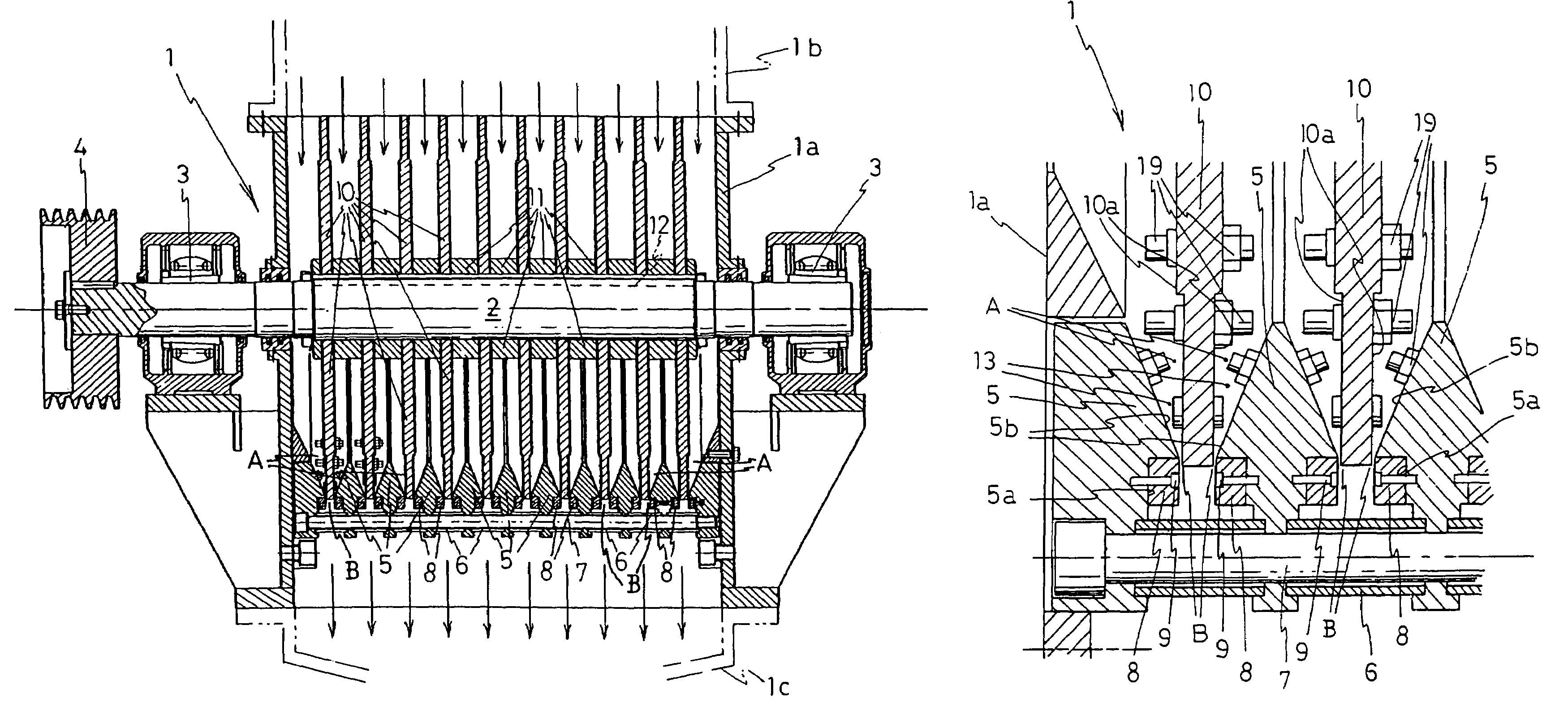
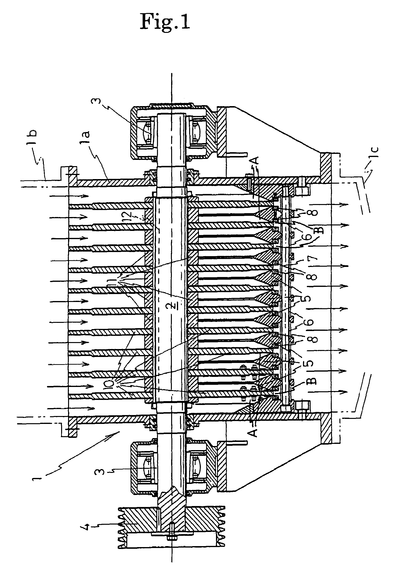
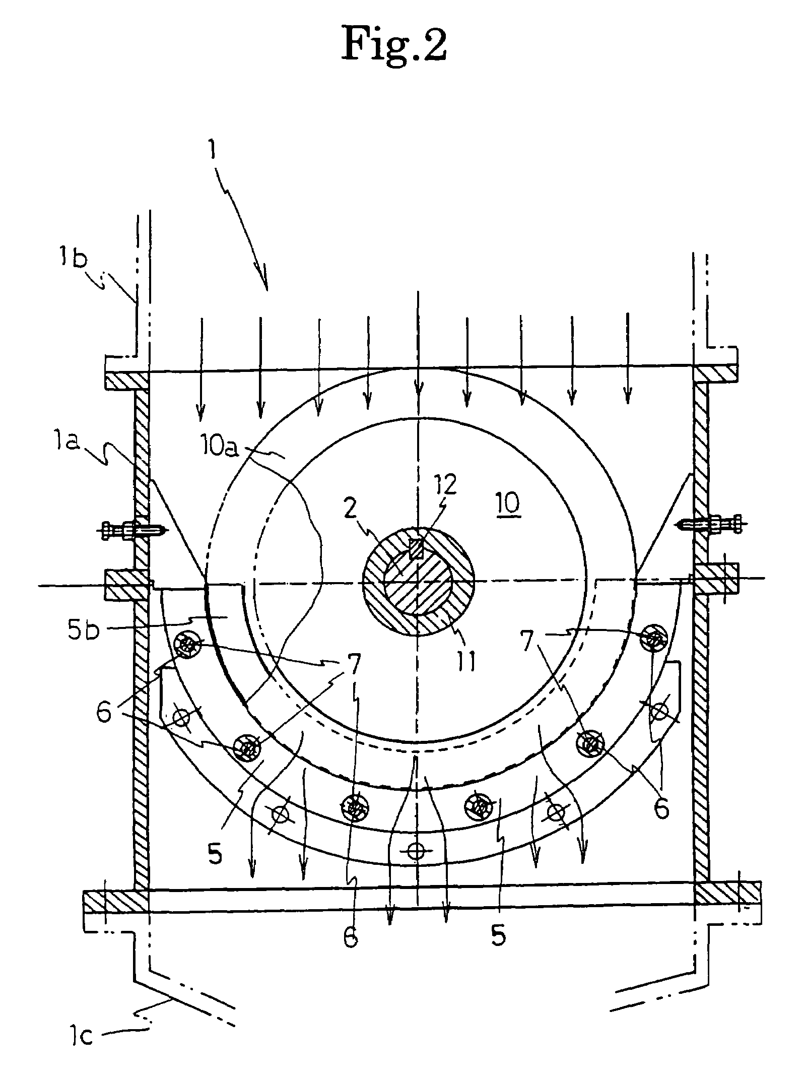
[0052]The particle crushing and sizing apparatus 1 according to the present invention illustrated in FIG. 1 has a rectangular casing body 1a. Inside this casing body 1a is provided horizontally a drive shaft 2, whose both ends project out of the casing body 1a through the side walls thereof. The two ends of the drive shaft 2 are supported by bearings 3, 3. A pulley 4 is provided on one end of the drive shaft 2; the pulley 4 is coupled to a motor pulley via a belt not shown in the figure.

[0053]Inside the casing body 1a are also provided a plurality of stators 5 of semi-circular shape having an isosceles triangle cross-section, the apexes whereof face the drive shaft 2, and through which is inserted a fixed shaft 7 disposed spanning the casing body 1a. The stators 5 are equidistantly separated by s...


PUM


Abstract

It is an object of the present invention to provide a particle crushing and sizing apparatus having a sufficiently wide particle crushing and sizing range, capable of being scaled down in size, and having high processing throughput. To achieve the object, a particle crushing and sizing apparatus has, in a casing 1a, a horizontally provided drive shaft 2, a plurality of circular plates 10 fixedly supported with intervals at the drive shaft 2, and stators 5 arranged so as to be opposed to plate faces 10a at lower peripheral edges of the circular plates 10 and each having inclined faces 5b that cause a gap between the plate faces 10a of the circular plates 10 to become narrower toward peripheral edges of the plate faces 10a. The plate faces 10a of the circular plates 10 and the inclined faces 5b of the stators 5 form gap portions A where particles are held, and particle crushing and sizing portions B are formed by the peripheral edges of the circular plates 10 and narrowest gap portions between the peripheral edges of the circular plates 10 and the inclined faces of the stators 5.

Description

TECHNICAL FIELD[0001]The present invention relates to a particle crushing and sizing apparatus for sizing into a predetermined particle size various wet or dry materials such as drugs, foodstuffs, fodders, chemicals, fertilizers, powdered coals, limestone, and ceramics materials which are granulated or formed by various apparatuses. More particularly, the present invention relates to a particle crushing and sizing apparatus for crushing wet aggregates or dry blocks, i.e., granulated materials (lumps) granulated or formed by various apparatuses and having particle size equal to or greater than a target value, and for sizing the crushed materials into a certain particle size range.BACKGROUND ART[0002]Particle mixing, granulating and sizing operations are widely employed in numerous industrial fields, such as in the pharmaceutical and food industries. The control of particle size is an important unit operation for improving particle handling, particle quality, fluidization during fluid...

Claims


Application Information

Patent Timeline
Patent Type & Authority Patents(United States)
IPC IPC(8): A47J19/00B02C17/02B07B13/00B02C7/06B02C7/11B02C7/12B02C13/22
CPCB02C7/06B02C7/11B02C7/12B02C13/22B02C7/16B02C7/188
Inventor NARA, YORIOKIHANADA, YOSHINORIHAMADA, KENJIWAKAMATSU, YOSHIHIROYAMAMOTO, SHINICHINAKAHARA, YUKO
Owner NARA MACHINERY
Why Eureka
Try Eureka