Method and apparatus for reducing visual aberrations

a technology of aberration and visual aberration, applied in the field of visual aberration correction, can solve the problems of affecting the normal operation of the eye, so as to reduce or eliminate the scarring caused by eye injury, reduce or eliminate the effect of visual aberration and small pupil

Inactive Publication Date: 2008-11-25
THE JOHN HOPKINS UNIV SCHOOL OF MEDICINE
View PDF7 Cites 1 Cited by
  • Summary
  • Abstract
  • Description
  • Claims
  • Application Information

AI Technical Summary

Benefits of technology

[0010]The invention solves the above problems by making use of the eye's natural response mechanism to control the amount of light that will enter the eye. Thus, light scattering caused by the corneal flap created during opthalmic surgery or scarring caused by eye injury will be reduced or eliminated resulting in reduction or elimination of visual aberrations. More specifically, to counteract the light scattering, the invention uses a light source to direct light toward the pupil of the eye at an intensity that causes the iris to constrict, resulting in a smaller pupil. The constricted pupil limits the light entering the eye to light that has passed through a smaller central circular portion of the cornea. Since the central cornea does not include the source of light scattering (flap margin area in LASIK, peripheral corneal wound or scar region), the visual aberration will be reduced or eliminated.

Problems solved by technology

For instance, with respect to laser vision correction surgery, halos, glare, starbursts and night vision difficulties are often found after laser in situ keratomileusis (LASIK).
Injury to the mid-periphery of the cornea can also cause similar visual aberrations due to scar formation or other corneal wound healing abnormalities.
When visual aberrations are present, they are disturbing at best and debilitating in the extreme.
For some individuals, night driving is difficult or impossible.
As noted, most of the above are general glare reduction systems not focused on solving the problems of visual aberrations caused by opthalmic surgery or injury.
Furthermore, the use of medicine can be considered invasive, and the optical methods can reduce the light signal.

Method used


Image

  • Method and apparatus for reducing visual aberrations
  • Method and apparatus for reducing visual aberrations
  • Method and apparatus for reducing visual aberrations

Examples


Embodiment Construction

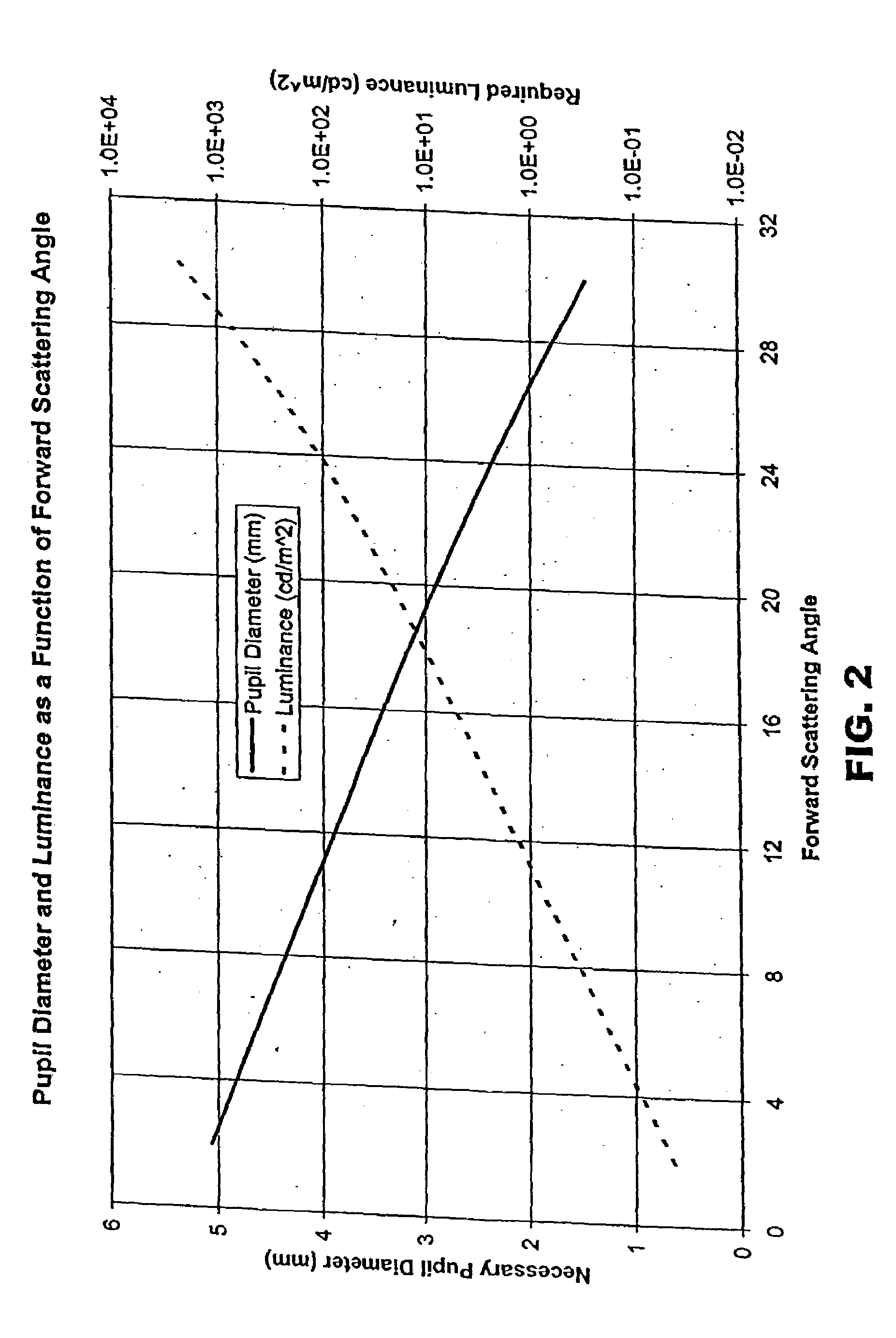
[0016]The present invention is counter-intuitive since it uses light itself to cause a restriction in the amount of light that can enter the eye. As is known, the human pupil responds to the exposure of light with maximum constrictive sensitivity to light of ˜560 nm (green-yellow); sensitivity is less in the blue and red portions of the spectrum. The diameter of the pupil is related to illumination. One measure of this relation is as follows:

log d=0.8558−0.000401(log b+8.60)3

where d is pupil diameter in mm and b is luminance in cd / m2. [Davson H. Physiology of the Eye, 5th Ed. Pergamon Press: New York; 1990, p. 757.] The pupil responds to both blinking and steady light. Direct light reflex is the constrictive response of the pupil to light on the eye, while indirect or consensual light reflex is the constrictive response of the pupil of the unstimulated eye. Stimulation of both eyes causes greater constriction of the pupils than light stimulation of a single eye.

[0017]The invention ...


PUM


Abstract

A light source is situated on a headgear device and placed to direct light toward the pupil of the eye at an intensity that causes the iris to constrict, resulting in a smaller pupil. This prevents the light scattering due to ophthalmic surgery or eye injury from entering the eye, thereby reducing or eliminating visual aberrations.

Description

CROSS-REFERENCE TO RELATED APPLICATIONS[0001]This application claims the benefit of prior filed U.S. application No. 60 / 704,402, filed on Aug. 1, 2005, the content of which is incorporated fully herein by reference.BACKGROUND OF THE INVENTION[0002]1. Field of the Invention[0003]This invention relates to a method and apparatus for correcting visual aberrations resulting from ophthalmic surgery or eye injury.[0004]2. Description of the Related Art[0005]Visual aberrations are sometimes found as complications following ophthalmic surgery or eye injury. For instance, with respect to laser vision correction surgery, halos, glare, starbursts and night vision difficulties are often found after laser in situ keratomileusis (LASIK). As shown schematically in FIG. 1, the aberrations are caused by light scattering that is thought to be localized in the vicinity of the outer circle of the corneal flap (flap margin) produced with a microkeratome as part of the LASIK procedure.[0006]A retrospectiv...

Claims


Application Information

Patent Timeline
Patent Type & Authority Patents(United States)
IPC IPC(8): A61B3/00A61B3/10
CPCG02C11/04A61F9/00
Inventor SILVER, DAVID M.CSUTAK, ADRIENNE
Owner THE JOHN HOPKINS UNIV SCHOOL OF MEDICINE
Why Eureka
Try Eureka