Differential scanning calorimeter

a scanning calorimeter and scanning calorimeter technology, applied in the direction of instruments, heat measurement, material heat development, etc., can solve the problems of inability to accurately perform sample analysis, inability to collect measurement, and deviation of the like in the joint face, so as to prevent the temperature rise of the second coil spring, improve reliability, and prevent the effect of mechanical property chang

Inactive Publication Date: 2008-11-25
HITACHI HIGH TECH SCI CORP
View PDF13 Cites 13 Cited by
  • Summary
  • Abstract
  • Description
  • Claims
  • Application Information

AI Technical Summary

Benefits of technology

[0015]In the differential scanning calorimeter concerned with this invention, since it has the heater and the cooling block, by heating or cooling an object article to be measured and the reference material, which have been accommodated in the accommodation chamber, a desired temperature can be easily produced. And, the differential heat flow detector detects the temperature difference between the sample to be measured and the reference material when the temperature in the accommodation chamber has been changed, and outputs the temperature difference having been detected as the heat flow difference signal. By obtaining this heat flow difference signal, a heat quantity that the sample to be measured excessively radiates or absorbs with respect to the reference material can be differentially detected, so that it is possible to perform a thermal analysis of the sample to be measured.
[0036]According to the differential scanning calorimeter concerned with the present invention, even if the heating and the cooling have been repeated, since it is possible to always stably maintain the heat flow path of at least any one of between the heat resistor and the accommodation chamber or between the heat resistor and the cooling block, it is possible to certainly obtain the heat flow difference signal having the reproducibility. Therefore, it is possible to highly precisely measure the sample to be measured, and the reliability can be improved.

Problems solved by technology

However, in the above conventional methods, the following problems are left.
However, the heat sink and the cooling device are not made by a material of completely the same quality, but generally are respectively made by utilizing materials of different qualities.
Therefore, when analyzing the sample, if the heating and the cooling are repeatedly performed, a distortion, a deviation and the like have occurred in a joint face due to a difference in thermal expansion coefficient.
As a result, a flow of the heat changes midway, so that there has existed a possibility that it is impossible to accurately perform the analysis of the sample.
Further, since the distortion and the deviation change every moment in compliance with conditions at that time, a reproducibility is bad, and it has been impossible to collect a measurement result and the like.

Method used


Image

  • Differential scanning calorimeter
  • Differential scanning calorimeter
  • Differential scanning calorimeter

Examples


Embodiment Construction

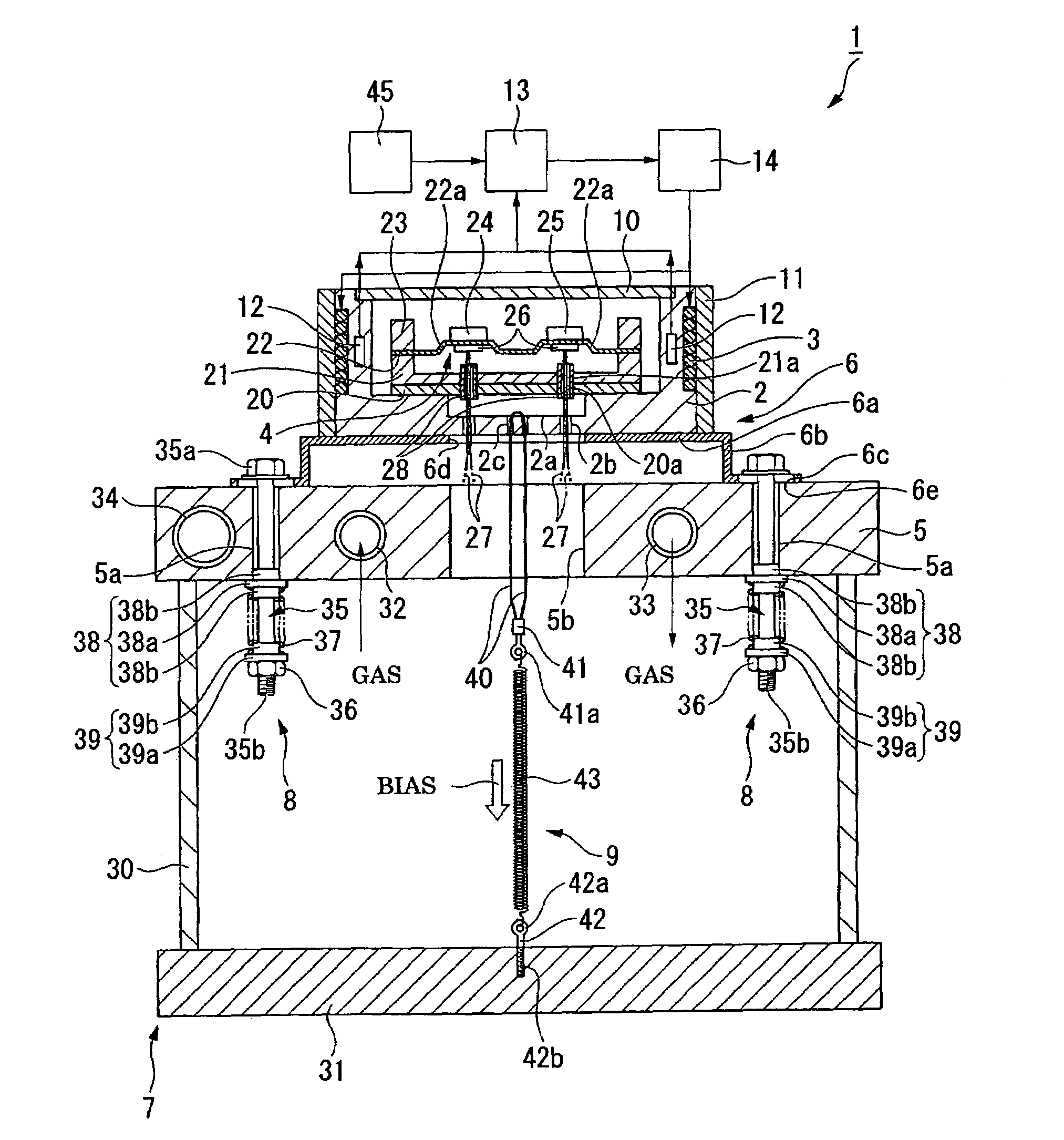
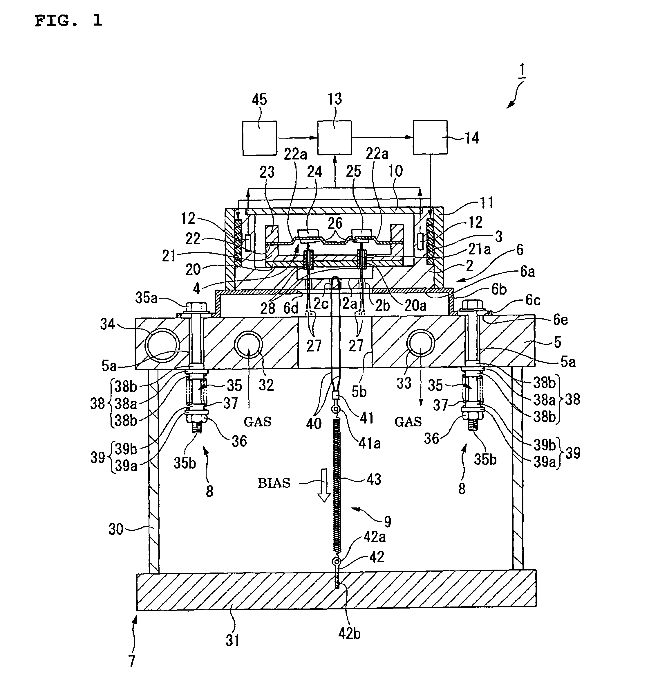
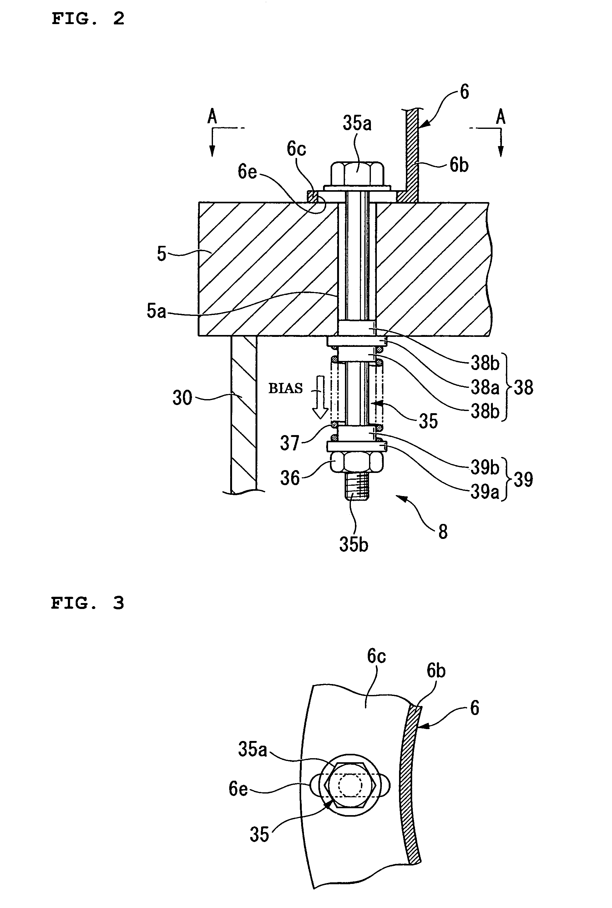
[0040]Hereunder, one embodiment of a differential scanning calorimeter concerned with the present invention is explained by referring to FIG. 1 to FIG. 3.

[0041]As shown in FIG. 1, a differential scanning calorimeter 1 of the present embodiment possesses a heat sink (accommodation chamber) 2 accommodating therein a sample to be measured and a reference material (both not shown in the drawing), a heater 3 attached so as to surround a periphery of the heat sink 2 and heating the heat sink 2, a differential heat flow detector 4 which is provided in the heat sink 2, detects a temperature difference between the sample to be measured and the reference material, and outputs the detected temperature difference as a heat flow difference signal, a cooling block 5 which is disposed below the heat sink 2 while being spaced by a certain distance, and cooling-controlled to a predetermined temperature, a heat resistor 6 which is formed so as to have a predetermined heat resistance, interposed betwe...


PUM

PropertyMeasurementUnit
temperatureaaaaaaaaaa

Abstract

There is provided a differential scanning calorimeter possessing an accommodation chamber accommodating a sample to be measured and a reference material, a heater heating the accommodation chamber, a differential heat flow detector outputting a temperature difference between the sample to be measured and the reference material as a heat flow difference signal, a cooling block cooling-controlled to a predetermined temperature, a heat resistor which mechanically connects the cooling block and the accommodation chamber and forms a heat flow path between both, a first fixation means which fixes the heat resistor to the cooling block by pressing the former while being biased by a constant elastic force, and a second fixation means which fixes the accommodation chamber to the heat resistor by pressing the former while being biased by a constant elastic force.

Description

[0001]This application claims priority under 35 U.S.C. §119 to Japanese Patent Application Nos. JP2006-019122 filed Jan. 27, 2006, the entire content of which is hereby incorporated by reference.BACKGROUND OF THE INVENTION[0002]The present invention is one relating to a thermal analysis apparatus measuring how physical properties of a sample change along with a temperature. Especially, it is one relating to a differential scanning calorimeter which, when the temperature has been changed, measures a heat quantity, that the sample excessively radiates or absorbs in comparison with a reference material, on the basis of a temperature difference (differential heat) between the sample and the reference material.[0003]The differential scanning calorimeter is an apparatus which, when the sample and the reference material (thermally stable material, e.g., alumina and the like) have been disposed while being juxtaposed and temperatures of both have been changed at a constant rate, differentia...

Claims


Application Information

Patent Timeline
Patent Type & Authority Patents(United States)
IPC IPC(8): G01N25/20
CPCG01N25/4866
Inventor NISHIMURA, SHINYA
Owner HITACHI HIGH TECH SCI CORP
Why Eureka
Try Eureka