
Sending radio station, receiving radio station, radio communication system, and radio communication method

a radio communication system and radio communication technology, applied in the field of radio communication systems, radio communication methods, and radio stations, can solve the problems of peculiar features of radio communications related to mobile communications, and achieve the effects of reducing the capacity of the receiving radio station, smooth handover, and effective utilization of frequency

Inactive Publication Date: 2008-11-25
NTT DOCOMO INC
View PDF20 Cites 9 Cited by
  • Summary
  • Abstract
  • Description
  • Claims
  • Application Information

AI Technical Summary

Benefits of technology

[0008]The present invention has been made in order to solve the above-mentioned problem, and the object of the invention is to provide a sending radio station, a receiving radio station, a radio communication system, and a radio communications method, whereby a smooth hand-over can be achieved.
[0028]Moreover, the following effects are also obtained incidentally. Since the guard band can be set small or can be unnecessary, the frequency can be effectively utilized. Moreover, since signals from a plurality of sending radio stations can be simultaneously received, multi-link transmission can be carried out. Moreover, new sending radio stations can be freely arranged without much taking into consideration the influence of interference of other existing sending radio stations forming the small cell. Furthermore, since the components for receiving of the receiving radio station which receive a plurality of frequency bands, can be shared, the reduction of capacity of the receiving radio station and the reduction of manufacturing cost can be achieved.

Problems solved by technology

However, the radio communications related to mobile communications has peculiar features, lacking in the communications of other fields, in that receiving radio stations, such as mobile terminals, move across various cells or areas.

Method used


Image

  • Sending radio station, receiving radio station, radio communication system, and radio communication method
  • Sending radio station, receiving radio station, radio communication system, and radio communication method
  • Sending radio station, receiving radio station, radio communication system, and radio communication method

Examples


first embodiment

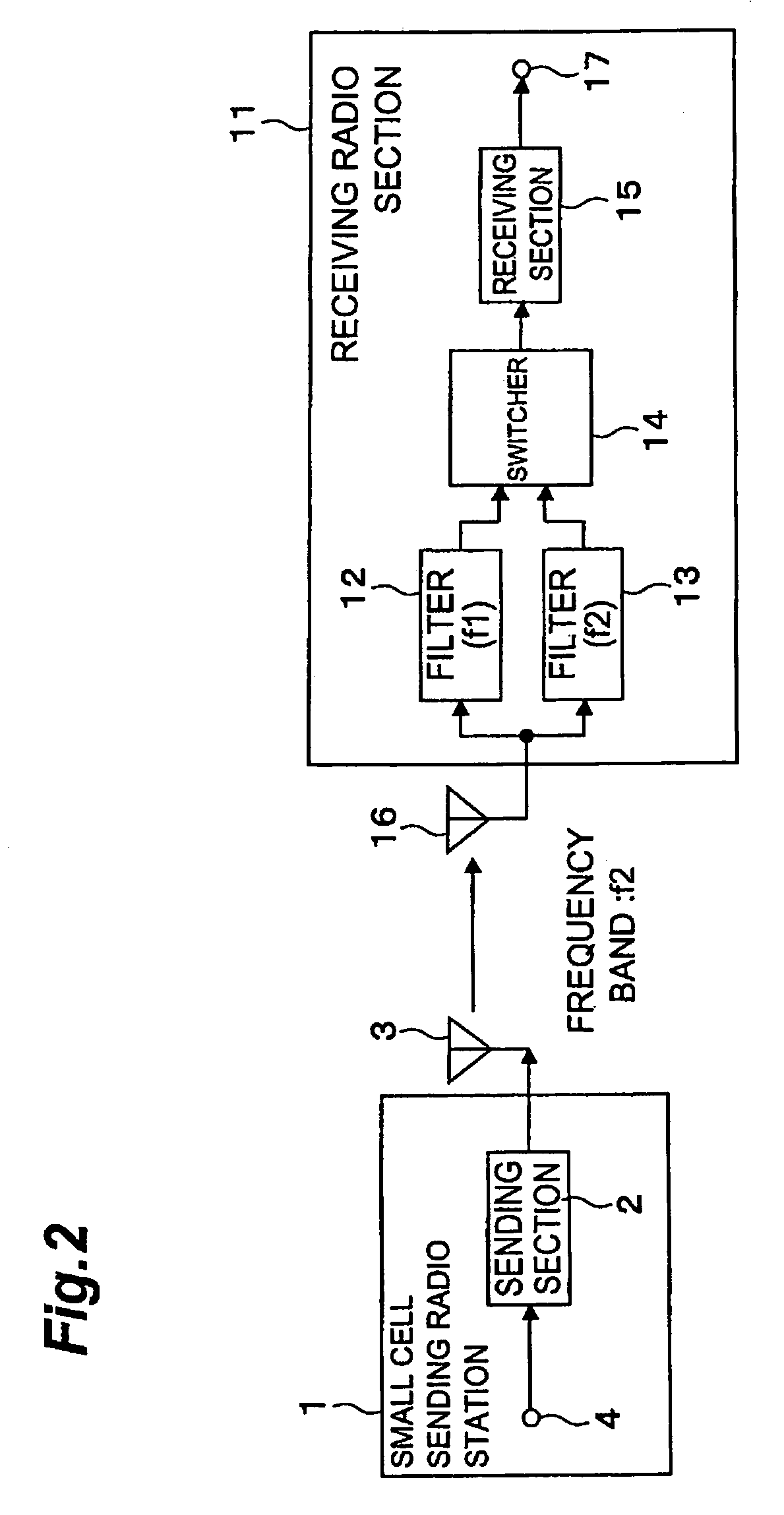
[0055]The first embodiment of the invention will be described using a view of the functional block configuration of a small cell sending radio station 101 and a receiving radio station 111 in FIG. 3, and a view showing the timing relationship of the receiving symbol from a large cell sending radio station and the sending symbol of a small cell sending radio station in FIG. 4. Moreover, a description will be made according to a case where the large cell sending radio station is using a frequency band f1 and the small cell sending radio station is using a frequency band f2. In addition, a “carrier frequency band” according to the present invention means a carrier frequency or a subcarrier frequency, and the sending radio station can send data by only one carrier.

[0056]In the small cell sending radio station 101, a symbol synchronization detection section 105 detects the symbol timing of the data which the large cell sending radio station sends, by receiving signals of the frequency ba...

second embodiment

[0091]Next, the second embodiment will be described using a view of the functional block configuration of the sending radio station and the receiving radio station of FIG. 6. This embodiment will be described as a case where a sending radio station uses a frequency band f3 and another sending radio station uses a frequency band f4. The sending radio station can be applied to both a large cell sending radio station and a small cell sending radio station. Moreover, although the case wherein two frequency bands are used will be described, such descriptive explanation is also adapted to the case wherein three or more frequency bands are used.

[0092]A sending section 202 of a sending radio station 201 and a sending section 202 of a sending radio station 221 will carry out the symbol synchronization for the sending symbols by means of the signal that is outputted from a symbol synchronization reference source 230. Namely, the data inputted from the data input terminal 4 of the sending radi...


PUM


Abstract

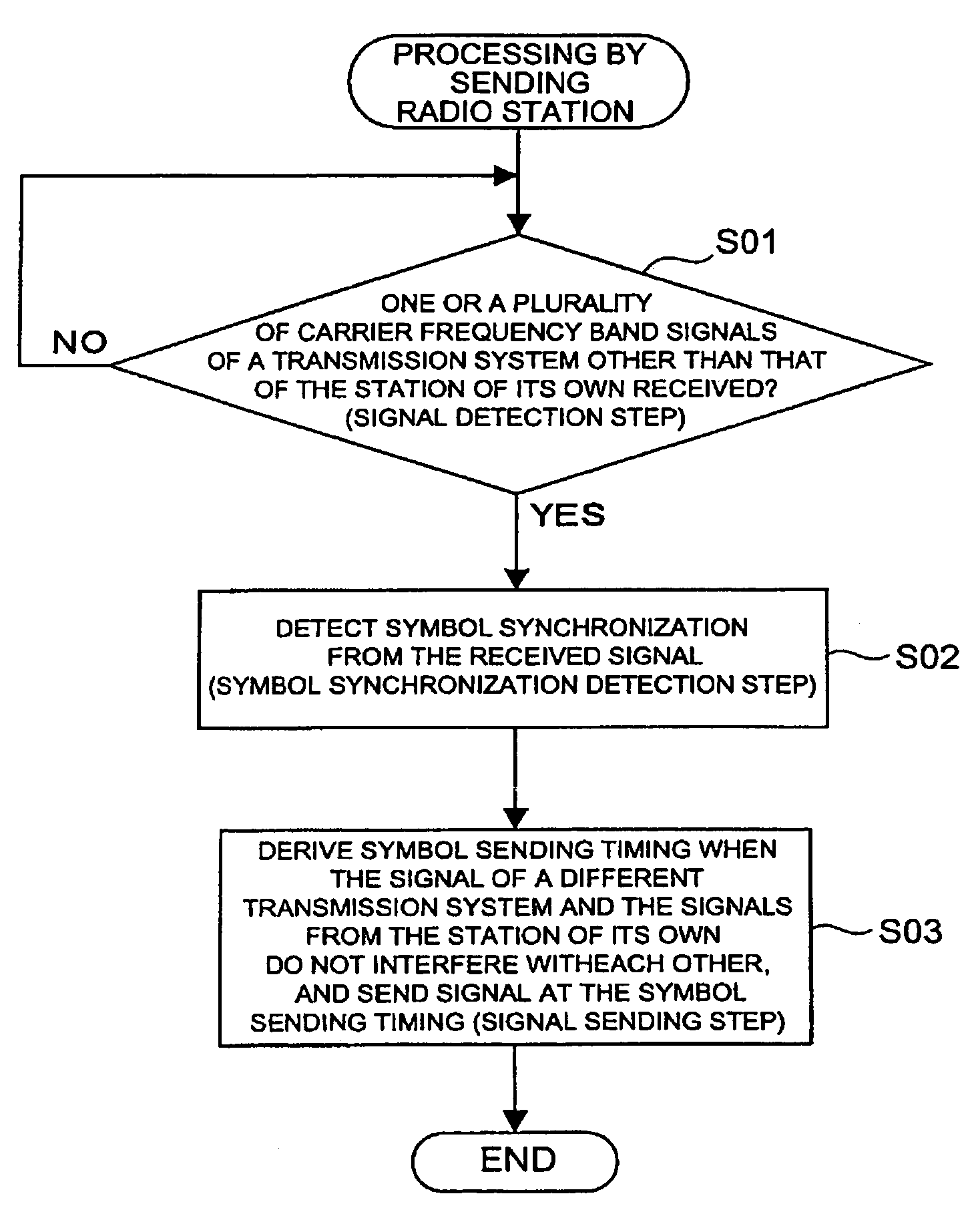
A method, device and system for arranging symbols to be sent in the frequency axis and for sending signals to a radio terminal inside an area using one or a plurality of carrier frequency bands, in a radio communication system with a hierarchical cell structure. The method includes detecting by a device at least one carrier frequency band signal pertaining to a transmission system other than that of its own station. A sending-symbol synchronization is detected based on at least one received signal upon detecting the carrier frequency band signal pertaining to the transmission system other than that of its own station. The signal is sent based on the derived symbol sending timing.

Description

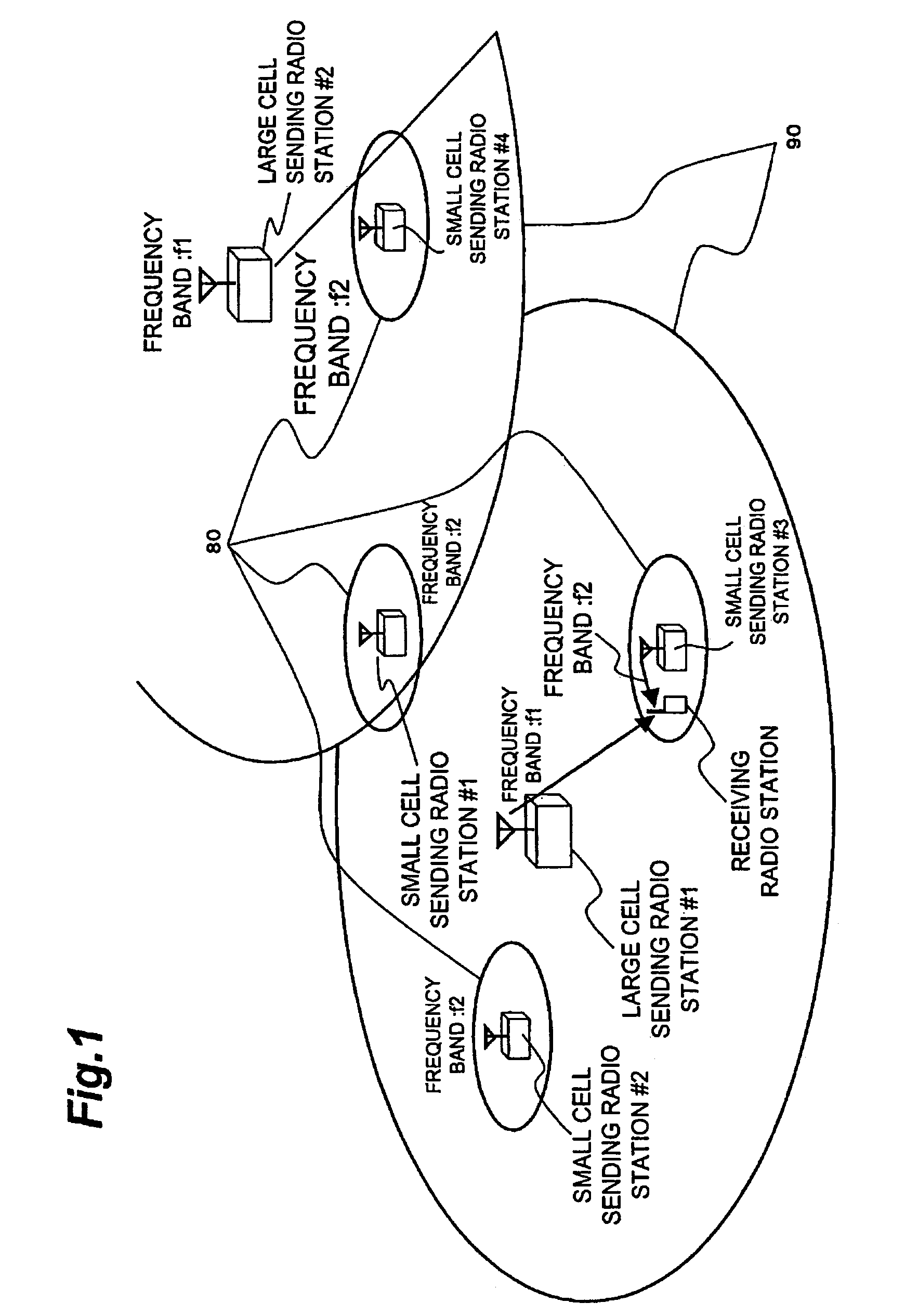
BACKGROUND OF THE INVENTION[0001]1. Field of the Invention[0002]The present invention relates to a sending radio station, a receiving radio station, a radio communication system, and a radio communication method in a radio communication system (for example, the radio communication system which executes OFDM (Orthogonal Frequency Division Multiplexing) transmission or OFCDM (Orthogonal Frequency Code Division Multiplexing) transmission) with a hierarchical cell structure (so-called cell-in-cell structure) for executing data transmission using orthogonal carrier frequency bands.[0003]2. Related Background Art[0004]In FIG. 1, there is shown a radio sending system using one or more sending radio stations which control a certain range of area 90, and a sending radio station forming a small scale cell 80 which can receive signal from the one or more sending radio stations and has smaller Equivalent Isotropically Radiated Power (EIRP) as compared with the one or more sending radio stations...

Claims


Application Information

Patent Timeline
Patent Type & Authority Patents(United States)
IPC IPC(8): H04Q7/36H04B7/26H04L27/26
CPCH04B7/2687H04L27/2662
Inventor OHKUBO, SHINZOOTSU, TORU
Owner NTT DOCOMO INC
Learn More