Recording method, recording medium and recorder

Inactive Publication Date: 2008-11-25
SHARP KK
View PDF36 Cites 10 Cited by
  • Summary
  • Abstract
  • Description
  • Claims
  • Application Information

AI Technical Summary

Benefits of technology

[0042]The twelfth and thirteenth aspects provide

Problems solved by technology

Use of a disk drive having high-speed reading writing performance is expensive compared to that of low speed.
Further, a higher power consumption is needed because of enhancement of the rota

Method used


Image

  • Recording method, recording medium and recorder
  • Recording method, recording medium and recorder
  • Recording method, recording medium and recorder

Examples


Embodiment Construction

[0066]Next, the embodiment of the present invention will be described with reference to the drawings.

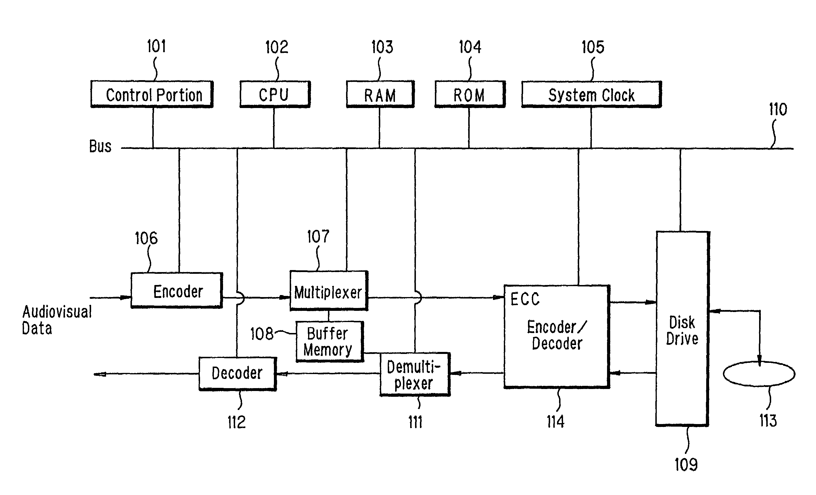
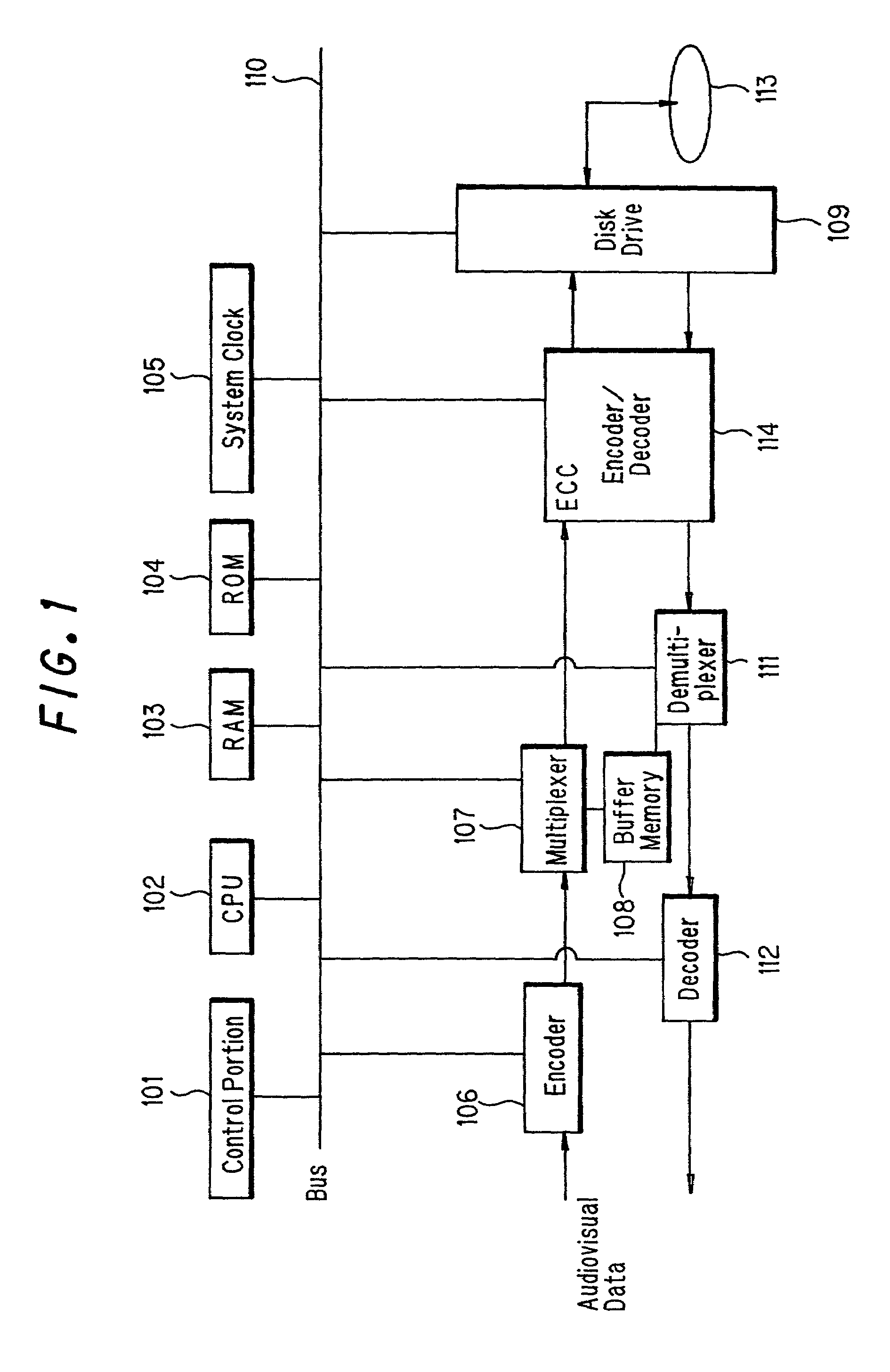
[0067]FIG. 1 shows a configuration of a video disk recorder according to one embodiment of the present invention, in which audio-dubbing function is made possible. As shown in the drawing, this apparatus is comprised of a control portion 101, CPU102, RAM 103, ROM 104, system clock 105, buffer memory 108, encoder 106, multiplexer 107, disk drive 109, bus 110, demultiplexer 111, decoder 112, disk 113 and ECC encoder / decoder 114.

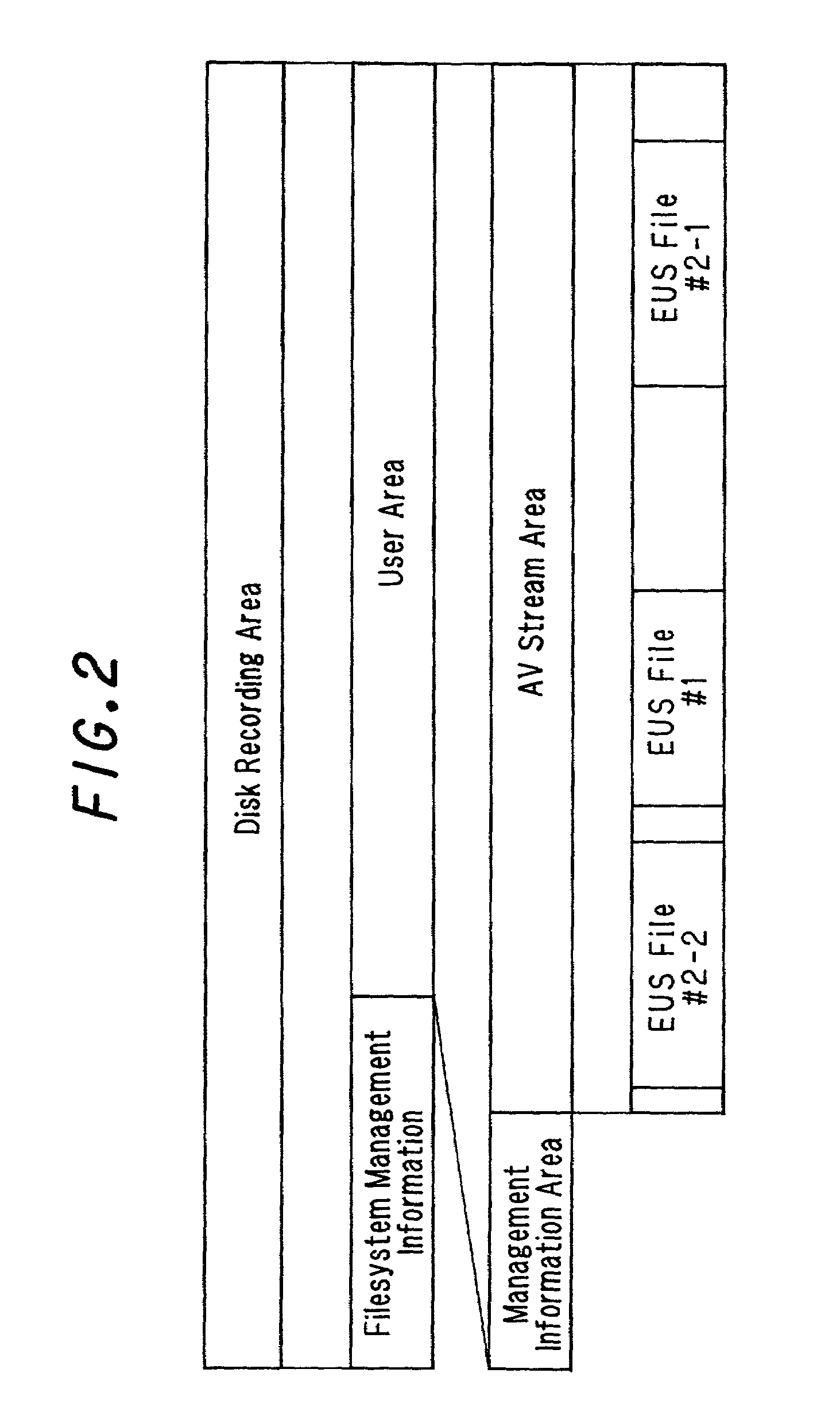
[0068]Disk 113 is assumed to be a removable optical disk which is recorded and played back spirally from the periphery toward the center. One sector is made up of 2048 bytes of data and sixteen sectors form one ECC block for error correction. If any data in an ECC block needs to be rewritten, it is necessary to read out the whole ECC block containing that data, subject it to error correction, renewing the target data, add error correction codes again to the data...


PUM


Abstract

When audio dubbing is implemented, error correction is performed for each ECC block. Therefore, even when one byte of data in an ECC block is rewritten, the whole ECC block to which the byte belongs needs to be read and rewritten. When audio dubbing data is scattered in ECC blocks, almost all ECC blocks, or all the data needs be rewritten in order to record audio dubbing data. By constructing ECC blocks including audio dubbing data so as not to contain original data, it is no longer necessary to read and rewrite unnecessary original data when audio dubbing data is overwritten.

Description

TECHNICAL FIELD[0001]The present invention relates to a process of recording video data and audio data onto, and playing back from a random-accessible recording medium such as hard disks, optical disks and the like.BACKGROUND ART[0002]Digital recording and reproduction apparatus for videos and audios using disk media have become widespread. In these apparatus, there is a demand for development of technologies which realize the audio-dubbing function at a low cost similar to tape media. The audio-dubbing function is a function which allows information, especially audios to be additionally recorded over already recorded audios and videos.[0003]Mentioned as a prior art example of realizing the audio-dubbing function with disk media is Japanese Patent Application Laid-Open Hei 5 No.234084. This technology, by taking advantage of the fact that the reading time of data is shorter than the program presentation time, writes input audio-dubbing data on the disk in the duration after the data...

Claims


Application Information

Patent Timeline
IPC IPC(8): H04N5/00G11B20/10G11B20/12G11B20/18G11B27/034G11B27/036H04N5/85H04N9/804H04N9/806H04N9/888
CPCG11B20/10527G11B27/036H04N9/8042H04N9/888G11B20/1813G11B27/034G11B2020/1062G11B2020/10833G11B2220/20G11B2220/216H04N5/85H04N9/8063G11B20/1217G11B20/1833G11B2020/10546G11B2020/10935G11B2020/1222G11B2020/1232G11B2020/1267G11B2220/2537
Inventor KIYAMA, JIROYAMAGUCHI, TAKAYOSHI
Owner SHARP KK
Why Eureka
Try Eureka