Heated medium supplying method and structure for secondary molding of resin molded component

a technology of resin molded components and supplying methods, which is applied in the direction of tubular articles, domestic applications, food shaping, etc., can solve the problems of reducing the deposition strength, hardening of resin materials, and deteriorating of deposition (joining after fusion) quality, so as to achieve convenient configuration

Inactive Publication Date: 2008-12-02
DENSO CORP
View PDF13 Cites 1 Cited by
  • Summary
  • Abstract
  • Description
  • Claims
  • Application Information

AI Technical Summary

Benefits of technology

[0014]In this way, the heated medium that has reached the predetermined temperature can be positively supplied into the flow path to heat the side wall of the flow path to at least the predetermined temperature. Thus, the resin material can be hardened uniformly to thereby improve the deposition quality while at the same time preventing the deposition strength from decreasing.
[0028]According to a seventh aspect of the invention, there is provided a heated medium supply structure in which the ejection port of the heated medium of the nozzle is formed in the side wall of the nozzle, and therefore the axial forward end can be closed by the wall. Thus, the second passage can be sealed with the forward end wall portion of the nozzle when the nozzle ejection port is located at such a position that the heated medium is ejected toward the first passage (bypass). As a result, a seal structure can be easily configured.

Problems solved by technology

If the secondary molding process is executed on the cooled and solidified primary molded component at room temperature, the secondary molding resin material injected is hardened so excessively that the problem is posed of a deteriorated deposition (joining after fusion) quality and a reduced deposition strength.
This promotes the hardening of the resin material injected and reduces the deposition strength.

Method used


Image

  • Heated medium supplying method and structure for secondary molding of resin molded component
  • Heated medium supplying method and structure for secondary molding of resin molded component
  • Heated medium supplying method and structure for secondary molding of resin molded component

Examples


Embodiment Construction

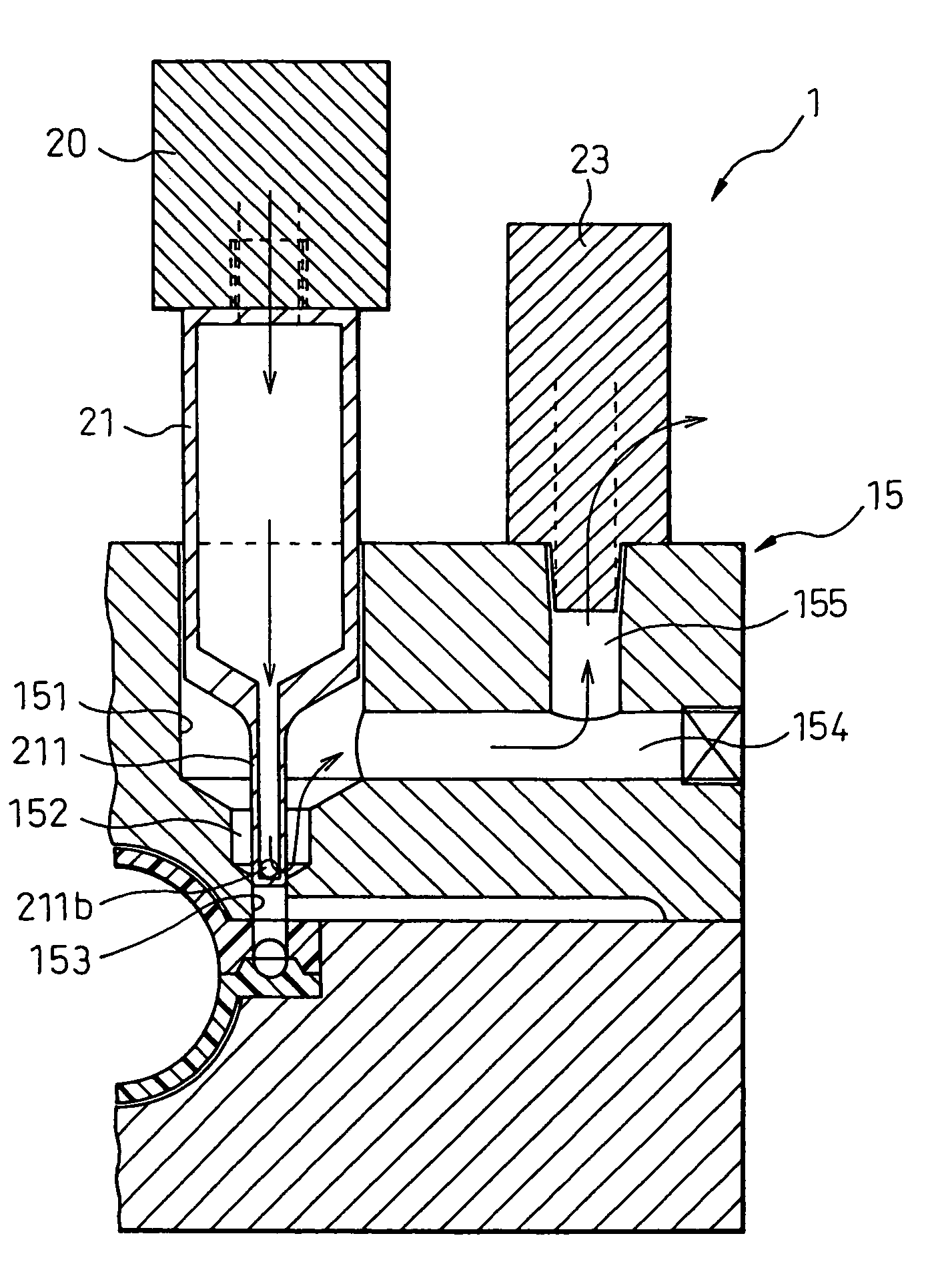
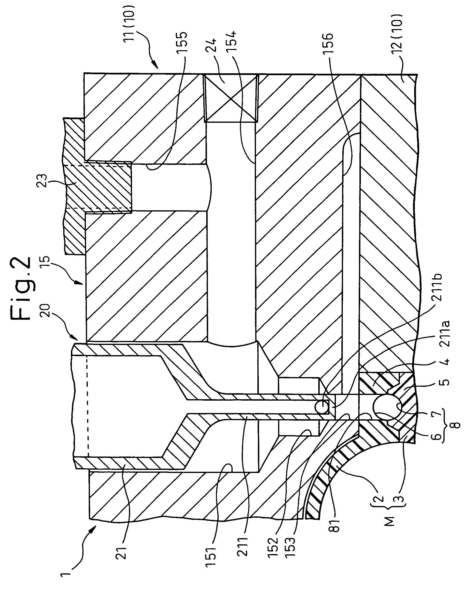
[0036]A heated medium supply structure used for secondary molding of a resin molded component according to this invention will be explained with reference to the drawings. The explanation of the present structure assumes that the resin molded component is an intake manifold of an automotive vehicle, and the heated medium is a heated air (hereinafter referred to as the hot air). In the description that follows, therefore, the heated medium supply structure is called a hot air supply structure.

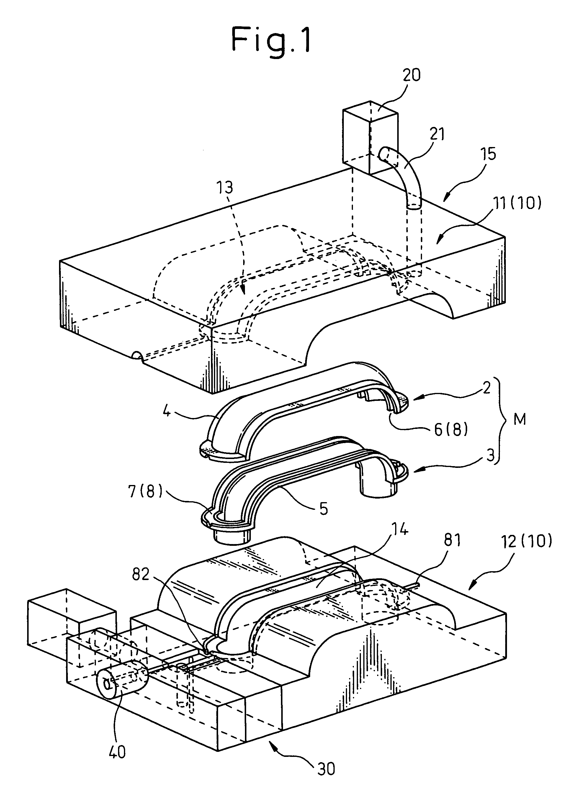
[0037]FIG. 1 shows the primary molded components 2, 3 of the intake manifold M set in an upper die 11 and a lower die 12 of a secondary molding die 10.

[0038]The primary molded components 2, 3 are formed with joins 4, 5, respectively, to couple the primary molded components 2, 3 to each other. Semicircular tubular paths 6, 7 are formed over the entire periphery of the coupling surface of the joins 4, 5. The tubular paths 6, 7 are each formed as a flow path (main path) 8 into which the secondary m...


PUM

PropertyMeasurementUnit
temperatureaaaaaaaaaa
timeaaaaaaaaaa

Abstract

A hot-air supply structure (1) comprises a hot air generator (20) and a housing (15) formed in the neighborhood of a hot-air inlet (81) of a molded component M in a die (10). A nozzle (21) is formed at the forward end of the hot-air generator, and an ejection port (211b) is formed on the side wall portion of the forward end needle unit (211) of the nozzle. The housing includes a support hole (151) in the nozzle, a relief hole (152), a flow path communication passage (153) and a bypass (154). The ejection port is movable between a first position to discharge the cool or warm air into the atmosphere through the bypass from the relief hole and a second position to introduce hot air into the flow path (8) of the molded component through the inlet (81) and the passage (153).

Description

BACKGROUND OF THE INVENTION[0001]1. Field of the Invention[0002]The present invention relates to a method and a structure for supplying a heated medium into a resin material injection path before injecting a resin material at the time of secondary molding of a primary molded resin component in which the heated medium is supplied.[0003]2. Description of the Related Art[0004]In processing a hollow resin molded component, e.g. an intake manifold of an automotive vehicle, a primary molded component is secondary molded. In the process, a plurality of primary molded components, segmented by the primary molding, are set in a secondary molding die. These primary molded components are butted against each other and a resin material flow path is formed at the butt junction of the primary molded components. Then, a secondary molding resin material is injected into the flow path thus formed. In this way, an intake manifold can be integrally formed as a resin molded component.[0005]In the case wh...

Claims


Application Information

Patent Timeline
Patent Type & Authority Patents(United States)
IPC IPC(8): B29C45/73B29C45/26B29C45/00B29C45/14B29C45/17B29C45/72B29L23/00
CPCB29C45/0062B29C66/54B29C2045/14877B29C65/103B29C65/42B29C65/542B29C66/0242B29C66/1312B29C66/547
Inventor NASU, HIDEHISAKUROYANAGI, AKIRAICHIKAWA, MASATOSAHASHI, AKIRA
Owner DENSO CORP
Why Eureka
Try Eureka