Fluid bearing unit and spindle motor using the same

a technology of fluid bearings and spindles, applied in the direction of sliding contact bearings, mechanical energy handling, mechanical apparatus, etc., can solve the problems of bearing units not being able to rotate, fluidity may be lost, and not being able to achieve the torque reduction. , to achieve the effect of low motor current consumption

Active Publication Date: 2008-12-02
NEW JAPAN CHEM CO
View PDF12 Cites 8 Cited by
  • Summary
  • Abstract
  • Description
  • Claims
  • Application Information

AI Technical Summary

Benefits of technology

[0011]According to the present invention, since an ester having low viscosity and excellent low temperature fluidity is used as the base oil of the lubricant, it is possible to realize a fluid bearing unit capable of being rotationally activated at lower torque even in an extremely low temperature region of not more than −40° C., and a spindle motor using the same.
[0020]According to a ninth aspect of the present invention, a spindle motor comprises the fluid bearing unit according to any one of the first to third aspects. With this configuration of the present invention, it is possible to realize a spindle motor having low motor current consumption.

Problems solved by technology

However, the conventional fluid bearing unit using such lubricant has a problem in that it can not sufficiently achieve the torque reduction as desired since the size of the bearing involved in miniaturization is limited.
However, since the monoester-based lubricant normally has a high pour point, there is a possibility in that the fluidity may be lost at a temperature of 0° C., moreover, at a low temperature region of not more than −20° C. and the lubricant may be solidified.
In the case of using the lubricant in a fluid bearing unit for portable equipment or in-vehicle equipment, the necessary torque of the bearing becomes considerably high under the necessary environment of not more than −40° C., so that there is a problem in that the bearing unit cannot be rotationally activated and the range of the operating temperature is limited.

Method used


Image

  • Fluid bearing unit and spindle motor using the same
  • Fluid bearing unit and spindle motor using the same

Examples


first embodiment

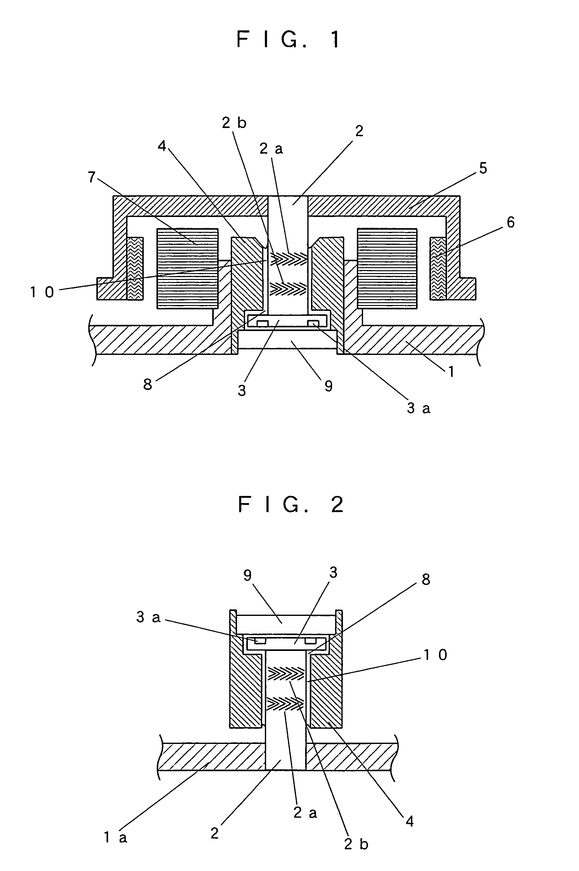
[0023]A fluid bearing unit according to first to eighth aspects of the present invention will now be described with reference to FIG. 2.

[0024]A shaft part has a configuration in that a thrust flange 3 is fixed to one end of a shaft 2 having an outer peripheral surface on which herringbone-shaped dynamic pressure generating radial grooves 2a, 2b are formed, and the other end of the shaft 2 is pressed and fixed to a base 1a.

[0025]The shaft part is inserted into a bearing hole of a sleeve 4. A thrust plate 9 is attached to the sleeve 4 so as to cover one side of the bearing hole and to face to the thrust flange 3. Further, spiral-shaped dynamic pressure generating thrust grooves 3a are formed on the surface of the thrust flange 3, which faces to the thrust plate 9. A gap between the bearing hole and the shaft part is filled with a lubricant 8.

[0026]As the sleeve 4 rotates, the lubricant 8 is collected by the dynamic pressure generating radial grooves 2a, 2b formed on the shaft 2 and p...

second embodiment

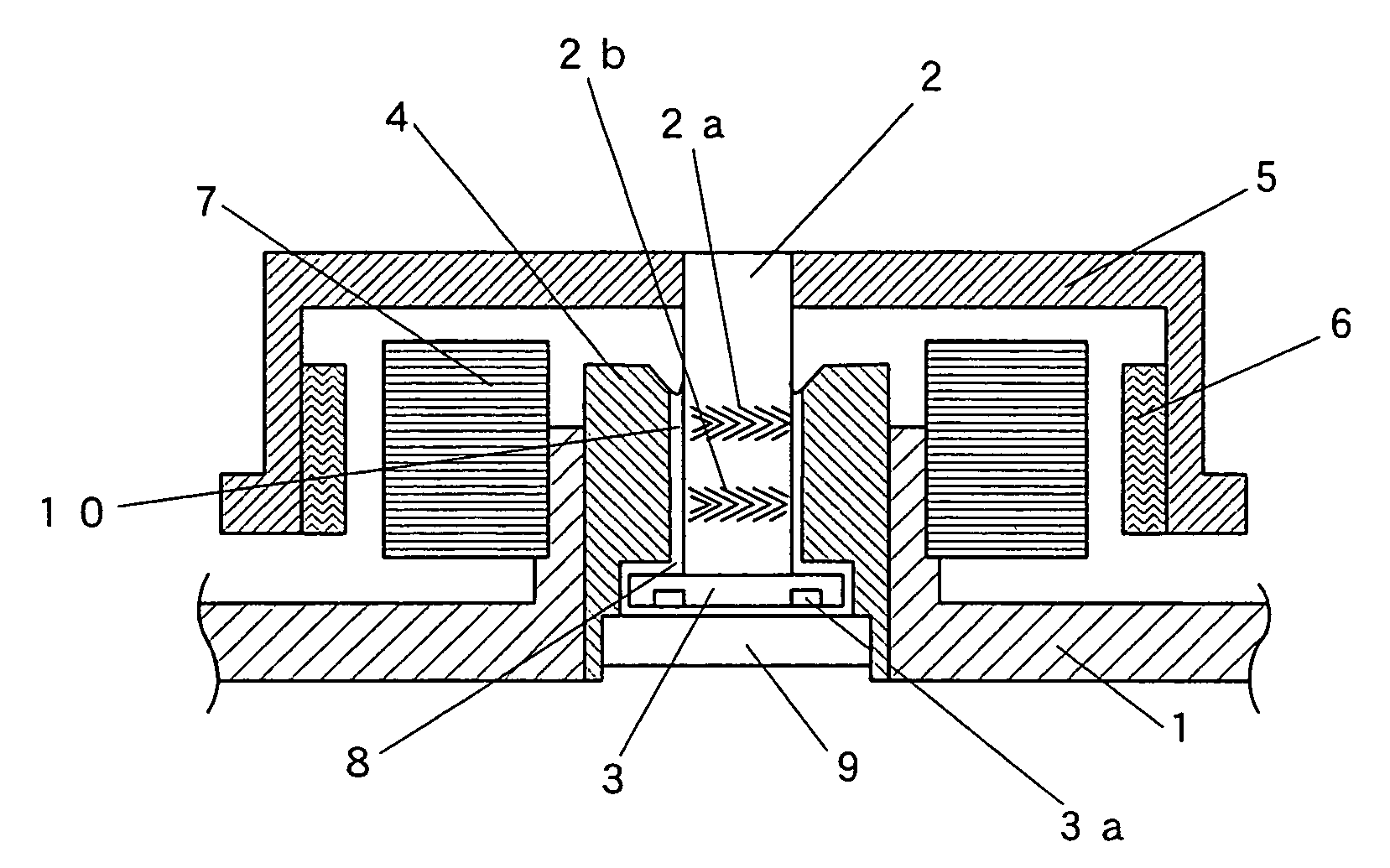
[0046]A spindle motor provided with a fluid bearing unit according to a ninth aspect of the present invention will now be described with reference to FIG. 1. Here, like reference characters designate corresponding parts of the fluid bearing unit of FIG. 2 according to the first embodiment, and thus the detailed description thereof is omitted. The fluid bearing unit of FIG. 1 differs from the fluid bearing unit of FIG. 2 in that the shaft fixation is modified to shaft rotation, and the dynamic pressure generating thrust grooves are a herringbone shape.

[0047]A thrust flange 3 is fixed to one end of a shaft 2 having an outer peripheral surface on which herringbone-shaped dynamic pressure generating grooves 2a, 2b are formed and a hub 5 for attaching a magnetic disc is pressed to the other end of the shaft 2, so that a rotating part is formed. A sleeve 4 for receiving the rotating part is pressed into a base 1, where a thrust plate 9 is attached on one end of the sleeve 4, thus forming ...

example 1

[0051]An ester derived from 3-methyl-1,5-pentanediol and n-heptanoic acid was used as a base oil.


PUM

PropertyMeasurementUnit
diameteraaaaaaaaaa
diameteraaaaaaaaaa
temperatureaaaaaaaaaa

Abstract

The present invention provides a fluid bearing unit capable of achieving lower torque and lower current consumption in comparison with a conventional bearing unit, and a spindle motor using the same. The present invention employs an ester derived from 1,5-pentanediol having one alkyl side chain and saturated monovalent fatty acid having 5 to 8 carbon atoms as a base oil of a lubricant with which a gap between a shaft and a sleeve is filled.

Description

BACKGROUND OF THE INVENTION[0001]1. Field of the Invention[0002]The present invention relates to a dynamic pressure-type fluid bearing unit used in a rotator device such as a magnetic disc drive, and a spindle motor using the same. More particularly, the present invention relates to a fluid bearing unit having a feature in means for reducing bearing torque and motor current consumption.[0003]2. Description of the Related Art[0004]A fluid bearing unit comprises a shaft and a bearing for receiving the shaft. As the fluid bearing unit rotates, a lubricant in a gap between the shaft and the bearing is collected by dynamic pressure generating grooves formed in one of the shaft and the bearing, so that pressure is generated in the gap and the shaft is supported by the bearing in a non-contact manner.[0005]A spindle motor provided with the fluid bearing unit is excellent in rotational accuracy which is indispensable in improving the recording density of a medium, impact resistance and nois...

Claims


Application Information

Patent Timeline
Patent Type & Authority Patents(United States)
IPC IPC(8): C10M105/38F16C32/06
CPCC10M107/20F16C17/107F16C33/109H02K7/085H02K7/086C10M2207/2815C10M2207/2825C10M2207/2835C10N2240/06C10N2240/204C10N2040/06C10N2040/18
Inventor HIRATA, KATSUSHISHIRAISHI, TAKANORI
Owner NEW JAPAN CHEM CO
Why Eureka
Try Eureka