Miniature patch antenna with increased gain

a patch antenna and patch antenna technology, applied in the field of manufacturing, can solve the problems of reducing the effectiveness of the antenna, reducing the distance, etc., and achieve the effect of more control

Active Publication Date: 2008-12-02
ORIGIN GPS LTD
View PDF20 Cites 15 Cited by
  • Summary
  • Abstract
  • Description
  • Claims
  • Application Information

AI Technical Summary

Benefits of technology

[0011]In some embodiments of the invention, more than two dielectric materials a

Problems solved by technology

On the other hand too big a distance also

Method used


Image

  • Miniature patch antenna with increased gain
  • Miniature patch antenna with increased gain
  • Miniature patch antenna with increased gain

Examples


Embodiment Construction

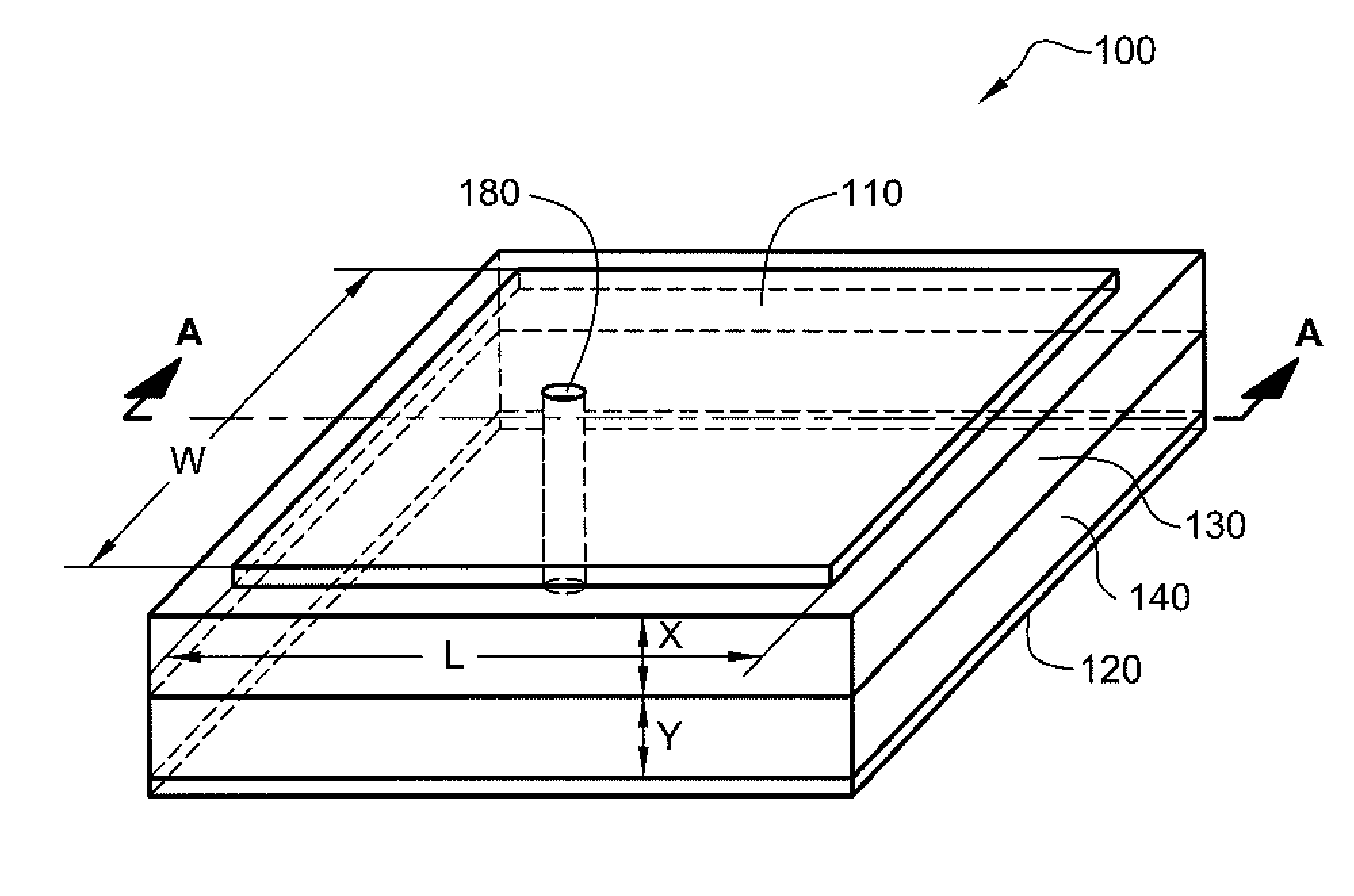
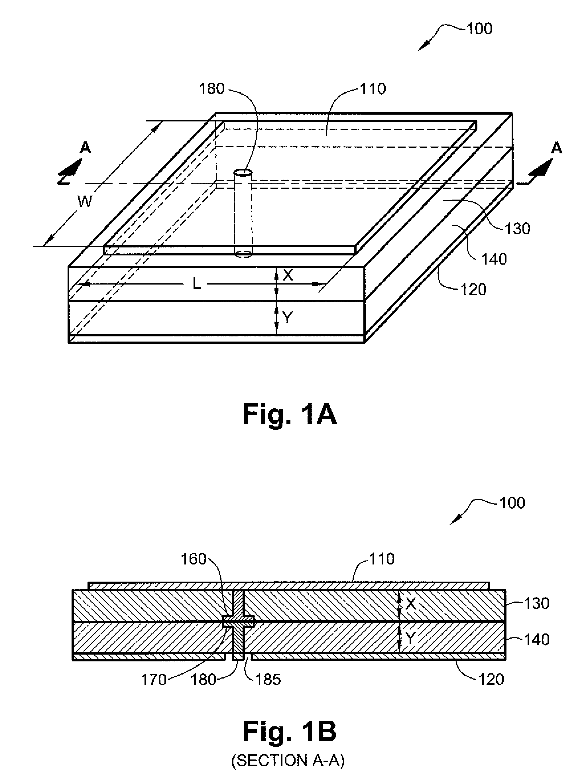
[0031]FIG. 1A is a schematic illustration of a perspective view of a patch antenna 100 with 2 layers of dielectric materials (130, 140) between the plates, according to an exemplary embodiment of the invention. In an exemplary embodiment of the invention, patch antenna 100 has a width W and a length L, wherein W and L may or may not be equal. As explained above the values of W and L are among the factors that determine the value of the dielectric constant needed between the plates of patch antenna 100. Patch antenna 100 includes a conducting patch plate 110 that is positioned in parallel to a ground plate 120. One of the dielectric material layers 140 serves in the antenna as a lower layer that is tangent to ground plate 120 and has a thickness Y. The second dielectric material layer 130 serves in the antenna as an upper layer that is tangent to patch plate 10 and has a thickness X. In an exemplary embodiment of the invention, the 2 dielectric layers (130, 140) affect the performanc...


PUM


Abstract

The present invention, relates to the preparation of a patch antenna with a specific effective dielectric constant; and a reduced dissipation factor. In an exemplary embodiment of the invention, size requirements and the desired resonant signal frequency dictate the permittivity value of the dielectric material to be used between the patch plate and the ground plate. Instead of using a dielectric material with the calculated permittivity value and its given dissipation factors a two layer dielectric of the same size with an effective dielectric constant that is equal to the desired dielectric constant, is used to replace the dielectric material and reduce the dissipation factor.

Description

FIELD OF THE INVENTION[0001]The present invention relates generally to the manufacture of miniature patch antennas and more specifically to increasing the gain provided by a specific size patch antenna.BACKGROUND OF THE INVENTION[0002]Patch antennas are very popular in telecommunication devices since they are rugged and are easily incorporated into the device. A patch antenna consists of a metal patch plate that is suspended over a metal ground plane. Generally the metal patch plate is essentially rectangular with an even or almost even width and length. The ground plate is generally the same size or slightly larger to provide optimal signal reception.[0003]Typically, a patch antenna with a vacuum between the plates has a resonant frequency for a signal when the patch plate has a length of about half the size of the wavelength of the signal, for example for a GPS signal with a frequency of approximately 1.5-1.6 GHz, half a wavelength would be about 95 mm. When manufacturing miniatur...

Claims


Application Information

Patent Timeline
IPC IPC(8): H01Q1/38
CPCH01Q1/38H01Q9/0407
Inventor GOLDBERGER, HAIM
Owner ORIGIN GPS LTD
Why Eureka
Try Eureka