Method of frame aggregation

a frame aggregation and frame technology, applied in the field of telecommunications, can solve the problems of delay-intolerant voice communications, delay-intolerant voice communications and other real-time and/or circuit switched services, and achieve the effect of reducing packet delay jitter and increasing the efficiency of channel bandwidth

Active Publication Date: 2008-12-02
LUCENT TECH INC
View PDF7 Cites 23 Cited by
  • Summary
  • Abstract
  • Description
  • Claims
  • Application Information

AI Technical Summary

Benefits of technology

[0020]The present invention provides a method of frame aggregation that reduces packet delay jitter and the delay for the first aggregate packet, as well as increases the efficient use of the channel bandwidth. More particularly, the method of the present invention provides a number of techniques for communicating at least one physical layer frames. For the purposes of the present disclosure, the term communicating corresponds with the transmission and reception of packetized data, including physical layer frames, for example, formed thereform.

Problems solved by technology

Voice communications are delay-intolerant by nature.
Voice communications and other real-time and / or circuit switched services have to date been viewed as delay-intolerant by nature.
Despite advances associated with processor speeds, the performance of forwarding algorithms and functions at each IP router utilizes precious router processing capacity and consequently limits the forwarding capacity of the routers.
Various problems, however, may arise when employing a voice frame aggregation of a fixed duration.
Longer packet transmission times may, for example, give rise to packet delay jitter when the channel data rate decreases.
Larger delays may also be anticipated for the first aggregated packet generated at the beginning of an ON period for a wireless unit.
This may transpire because the resources have been released during the wireless unit's OFF period and additional access delay may also be applied to the packet itself.
Finally, voice frame aggregation of a fixed duration may be inefficient in its use of channel bandwidth.

Method used


Image

  • Method of frame aggregation
  • Method of frame aggregation
  • Method of frame aggregation

Examples


Embodiment Construction

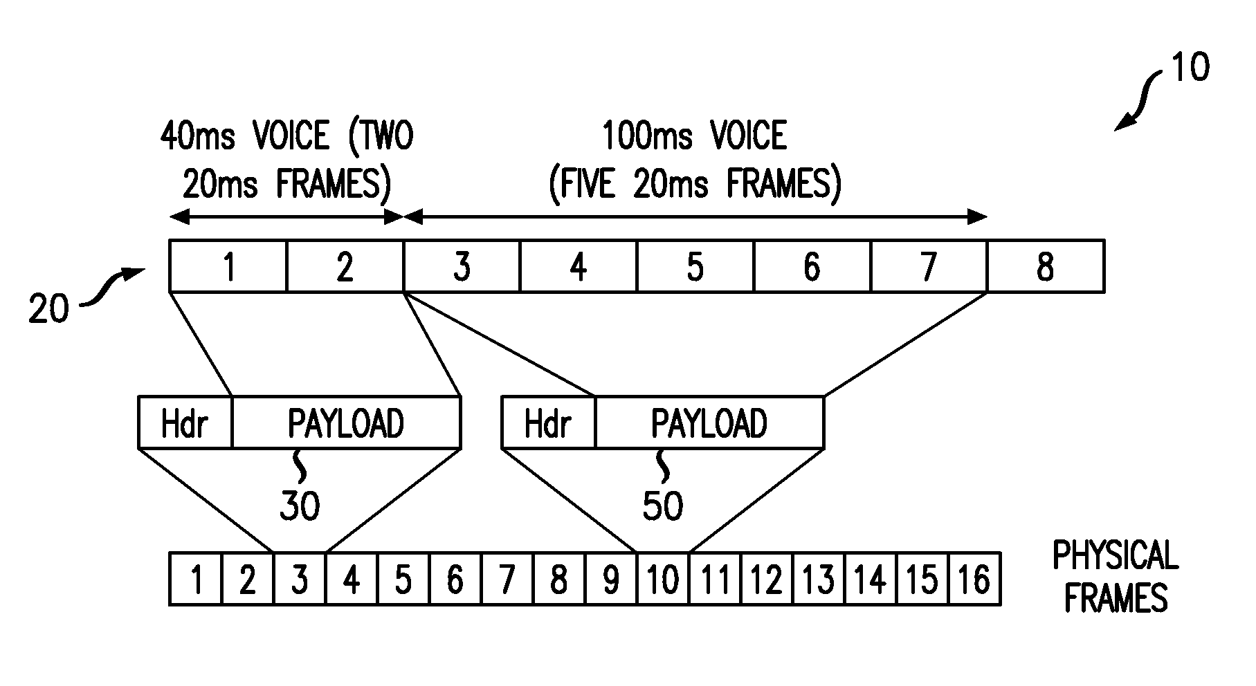
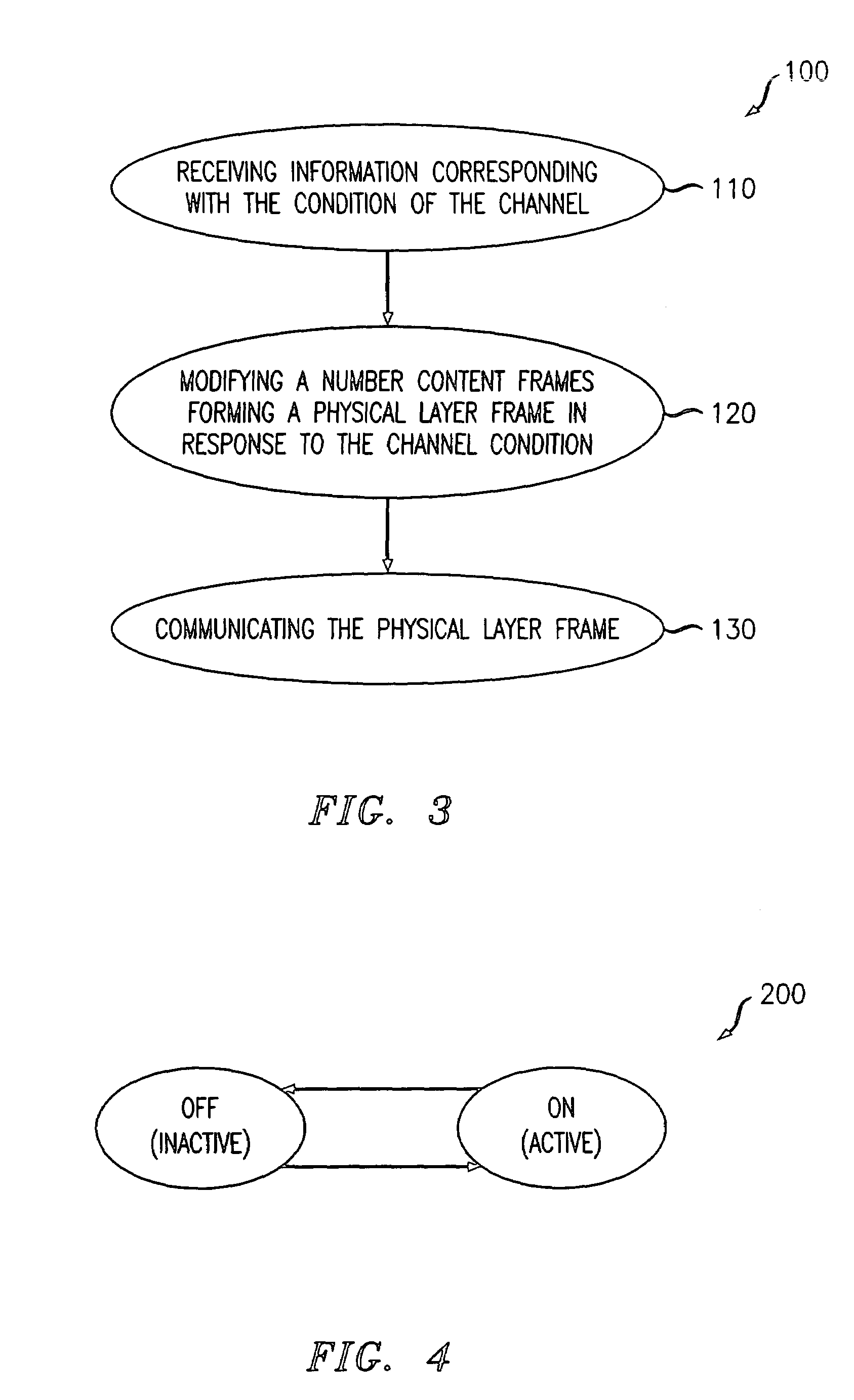
[0037]The present invention provides a method of frame aggregation that reduces packet delay jitter and the delay for the first aggregate packet, as well as increases the efficient use of the channel bandwidth. More particularly, the method of the present invention provides a number of techniques for communicating at least one physical layer frames. For the purposes of the present disclosure, the term communicating corresponds with the transmission and reception of information, signals and packetized data, for example, including physical layer frames, formed therefrom.

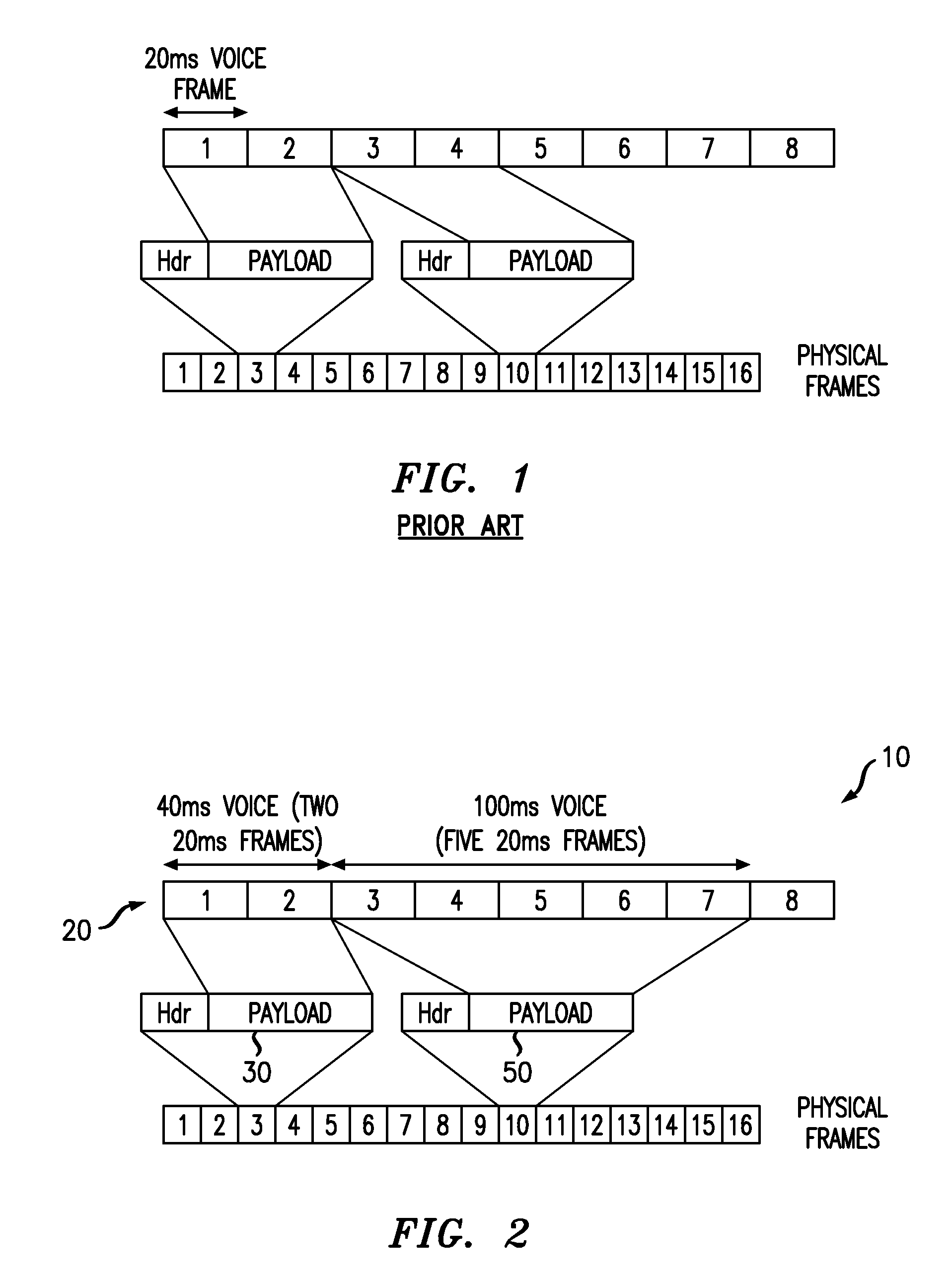
[0038]Referring to FIGS. 2 and 3, aspects of an embodiment of the present invention are illustrated. FIG. 2 depicts an exemplary configuration 10 of a variable packet size aggregation technique. More particularly, this technique reduces the likelihood of retransmission and therefore delay by considering the channel quality and system load, for example. As the channel quality varies, so too does the available data rate,...


PUM


Abstract

A method of the communication includes communicating at least one physical layer frame. The physical layer frame is formed by dynamically varying an aggregate packet size in response to a condition of a channel used for communicating voice and / or data. Here, the step of dynamically varying aggregate packet size may involve modifying a number of content frames to form the physical layer frame. The physical layer frame may correspond with a payload having at least two content frames and at least one IP header. Each content frame may include a voice frame and / or a data frame.

Description

BACKGROUND OF THE INVENTION[0001]1. Field of the Invention[0002]The present invention relates to telecommunications, and more particularly, to wireless and wireline communications.[0003]2. Description of the Related Art[0004]Wireless communications systems provide wireless service to a number of wireless or mobile units situated within a geographic region. The geographic region supported by a wireless communications system is divided into spatially distinct areas commonly referred to as “cells.” Each cell, ideally, may be represented by a hexagon in a honeycomb pattern. In practice, however, each cell may have an irregular shape, depending on various factors including the topography of the terrain surrounding the cell. Moreover, each cell is further broken into two or more sectors. Each cell is commonly divided into three sectors, each having a range of 120 degrees, for example.[0005]A conventional cellular system comprises a number of cell sites or base stations geographically dist...

Claims


Application Information

Patent Timeline
Patent Type & Authority Patents(United States)
IPC IPC(8): H04L12/66H04J3/16H04B7/26H04L12/56H04L29/06
CPCH04L1/0007H04B7/2656H04L1/0018H04L1/0027
Inventor KHAN, FAROOQ ULLAH
Owner LUCENT TECH INC
Why Eureka
Try Eureka