Method of controlling the combustion phase of an internal-combustion engine, notably a gasoline type direct-injection supercharged engine

a combustion phase and combustion chamber technology, applied in the direction of electric control, brake systems, instruments, etc., can solve the problems of affecting the combustion phase of the engine, so as to and reduce the pressure in the combustion chamber.

a combustion phase and combustion chamber technology, applied in the direction of electric control, brake systems, instruments, etc., can solve the problems of affecting the combustion phase of the engine, so as to and reduce the pressure in the combustion chamber.

US7461633B2Inactive Publication Date: 2008-12-09INST FR DU PETROLE

Image

  • Method of controlling the combustion phase of an internal-combustion engine, notably a gasoline type direct-injection supercharged engine
  • Method of controlling the combustion phase of an internal-combustion engine, notably a gasoline type direct-injection supercharged engine

Examples


Embodiment Construction

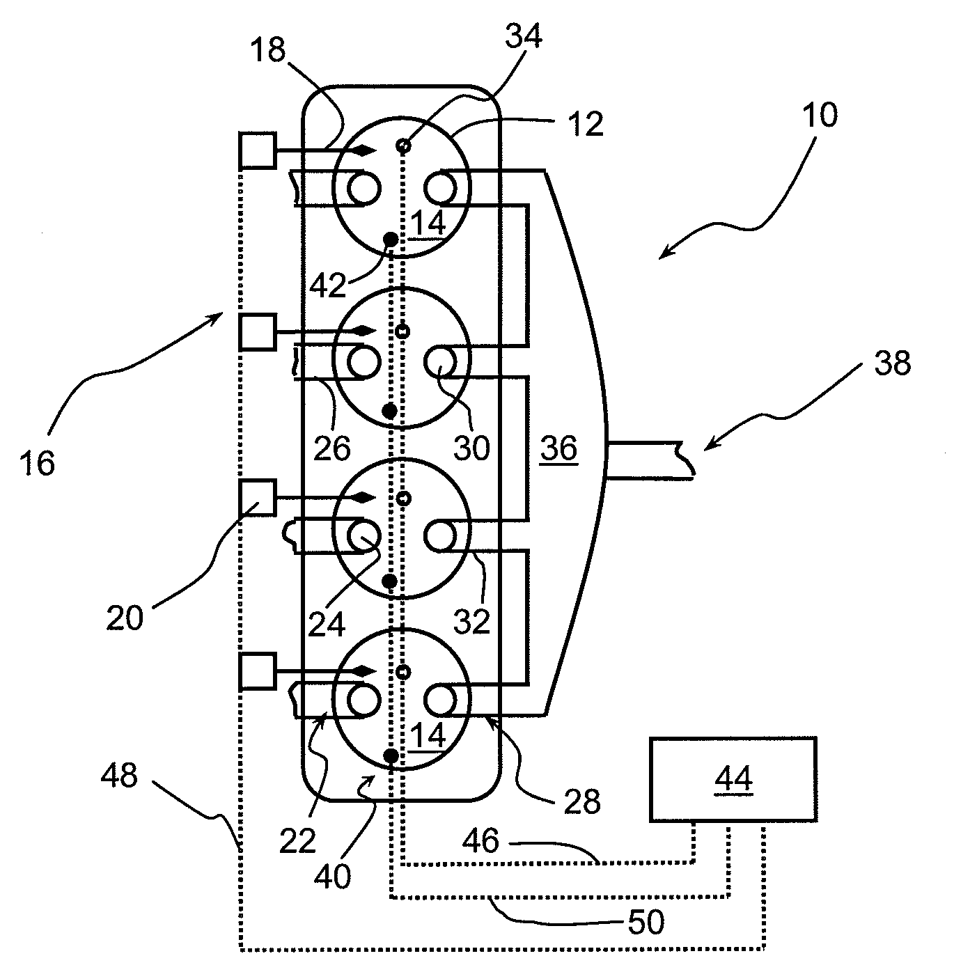
[0031]FIG. 1 shows an example of a gasoline type spark-ignition supercharged internal-combustion engine 10. Of course, any other type of spark-ignition engine, such as an engine running on gas, VNG or LPG for example, can also be used. This engine comprises at least one cylinder 12 with a combustion chamber 14 generally delimited by the inner wall of the cylinder, the part of the cylinder head opposite the piston and the top of the piston. It is in this chamber that combustion of a mixture of air, preferably supercharged, and of fuel, gasoline here, occurs among other things.

[0032]The cylinder comprises at least one means 16 for delivering fuel under pressure, for example in form of a fuel injection nozzle 18 that opens into the combustion chamber and is controlled by a valve 20. This cylinder also comprises at least one air supply means 22 with a valve 24 associated with an intake pipe 26, at least one burnt gas exhaust means 28 with a valve 30 and an exhaust pipe 32, and at least ...


PUM


Abstract

Method of controlling the combustion of an internal-combustion engine, in particular a direct-injection supercharged engine, notably of gasoline type, wherein the engine comprises at least one cylinder (12) with a combustion chamber (14) within which a compression stage takes place, followed by a stage of combustion of a fuel mixture by a spark-ignition means (34), characterized in that it consists in measuring a quantity related to at least one parameter representative of the state of the fuel mixture during said stages; in determining a value that depends on the amplitude of the measured quantity; in comparing the determined value with at least one threshold value representative of the quantity related to said parameter representative of the conventional state of the fuel mixture during said stages; in detecting the start of an abnormal combustion when the determined value exceeds said threshold value and when the ignition means is not actuated; in controlling the course of the abnormal combustion detected in the combustion chamber.

Description

FIELD OF THE INVENTION[0001]The present invention relates to a method of controlling the combustion phase of an internal-combustion engine.[0002]It more particularly relates to a method intended for a spark-ignition engine, preferably of gasoline type, and notably an advantageously direct-injection supercharged engine.BACKGROUND OF THE INVENTION[0003]This type of engine includes at least one cylinder comprising a combustion chamber delimited by the inner lateral wall of the cylinder, by the top of the piston that slides in this cylinder and by the cylinder head. Generally, a fuel mixture is contained in this combustion chamber and it undergoes a compression stage, then a combustion stage under the effect of a spark ignition, such as a spark plug, these stages being grouped together under the term “combustion stage” in the description hereafter.[0004]It has been observed that this fuel mixture can undergo various combustion types and that these combustion types are the source of diff...

Claims


Application Information

Patent Timeline
09 Dec 2008
Publication
US7461633B2
IPC
F02M1/00; B60T7/12
CPC
F02D35/02; F02D41/1497; F02D41/22; F02D35/028; F02D13/02; F02D15/04; F02D35/023; F02D35/027
Inventors
VANGRAEFSCHEPE, FRANCK; ZACCARDI, JEAN-MARC