Fully-enclosed fan-cooled motor

a fully enclosed, fan-cooled technology, applied in the direction of magnetic circuit rotating parts, magnetic circuit shapes/forms/construction, packaged goods types, etc., can solve the problems of reducing the amount of ventilation within the motor, requiring a large amount of labor, and a considerable obstacle to implementing an ideal fully enclosed fan-cooled motor. , to achieve the effect of suppressing the rise in the temperature of the bearing greas

Active Publication Date: 2008-12-09
KK TOSHIBA
View PDF7 Cites 35 Cited by
  • Summary
  • Abstract
  • Description
  • Claims
  • Application Information

AI Technical Summary

Benefits of technology

[0027]An object of the present invention is therefore to provide a fully-enclosed fan-cooled motor wherein the heat-generating bodies such as the stator coils or rotor bars can be effectively cooled and, as a result, wherein rise in temperature of the bearing grease can be suppressed.
[0039]With a fully-enclosed fan-cooled motor according to the present invention, heat-generating bodies such as the stator coils or rotor bars can be effectively cooled and, as a result, the rise in temperature of the bearing grease can be suppressed and the bearing lubrication life consequently greatly extended. Also there is no contamination of the interior of the motor, so an ideal motor can be provided in which labor-saving in regard to maintenance can be achieved.

Problems solved by technology

However, the external air that is drawn in represents a severely polluted environment in that large quantities of dust are present entrained in the external air around a motor that is mounted on the underfloor chassis of an electric car or the like during vehicle running.
Consequently, in a motor according to the conventional example illustrated in FIG. 1, there was the technical problem that, although an attempt was made to clean the external air that was drawn into the motor by capturing the dust by the filter 115a of the ventilation filter 115, with continuous operation, gradual blockage of the filter 115a took place, decreasing the amount of ventilation within the motor; periodic cleaning / maintenance of the filter was therefore required at short intervals, requiring the expenditure of a very considerable amount of labor.
However, in such a typical fully-enclosed fan-cooled motor, although the heat generated by the stator coils 212 can be discharged to the external atmosphere from the ventilation passages 201a by being transmitted through the core 208 and frame 201, there were the following problems, which presented a considerable obstacle to implementing an ideal fully-enclosed fan-cooled motor.
If the bearing grease is raised to a high temperature, its lubrication life becomes short and, as a result, the maintenance recursiveness (maintenance recurrence or maintenance period) of the motor cannot be extended.
Thus, as a countermeasure, there was no alternative to designing a conventional fully-enclosed fan-cooled motor in such a way as to suppress generation of heat by the rotor, to ensure that the permitted temperature of the bearing grease was secured: the result was to present obstacles to design of a motor having a larger rotor than normal and offering high output with small size and light weight.

Method used


Image

  • Fully-enclosed fan-cooled motor
  • Fully-enclosed fan-cooled motor
  • Fully-enclosed fan-cooled motor

Examples


third embodiment

[0079]Next, a third embodiment of the present invention is described. FIG. 6 is an axial cross-sectional view of a third embodiment.

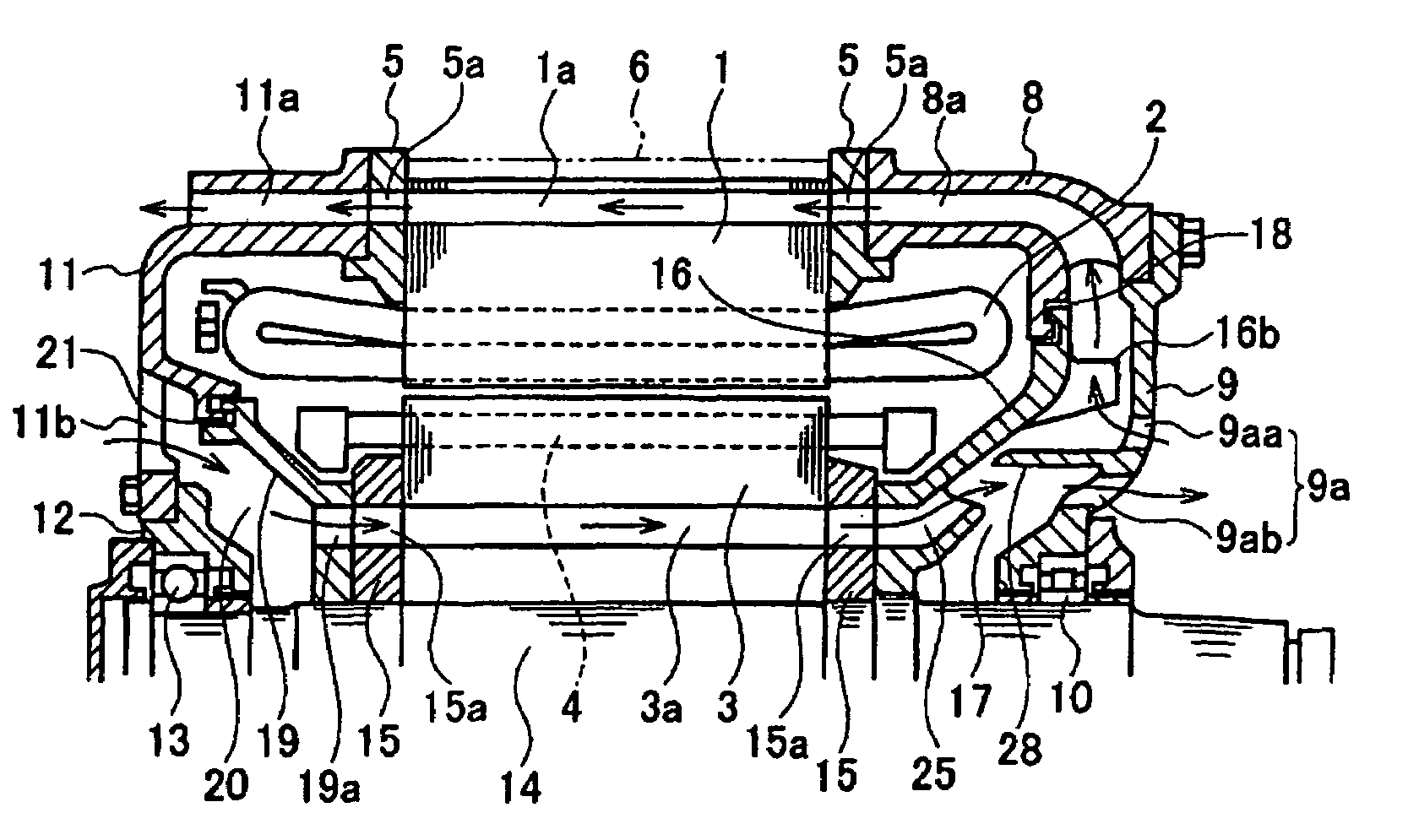
[0080]In this embodiment, in order that dust should not accumulate in the ventilation passage 3a, a ventilation fan 25 dedicated to the rotor core that sucks out air in the ventilation passage 3a is formed above the ventilation fan 16. Since the ventilation passage 38 is formed in the rotor core, which is rotating, if the centrifugal force produced by the rotation of the ventilation passage 3a becomes larger than the suction force produced by the negative pressure of the ventilation fan 16, dust may be deposited and can easily accumulate in the region outside the outer periphery of the inner surface of the ventilation passage 3a. The suction pressure must be increased in order to reduce such accumulation of dust.

[0081]Although the suction negative pressure can be increased by making the diameter of the ventilation fan 16 larger, practically all of the a...

fourth embodiment

[0082]Next, a fourth embodiment of the present invention will be described. FIG. 7 is an axial cross-sectional view of the fourth embodiment.

[0083]In this embodiment, the aperture 9a of the bearing bracket 9 is eliminated from the construction of the third embodiment, so intake of external air only takes place from the aperture 11b of the second bracket 11. In this case, compared with the third embodiment, the cooling properties regarding the rotor core 3 are inferior, but manufacture is facilitated since no aperture 9a is provided in the bearing bracket 9: the advantage is therefore obtained that manufacturing costs can be reduced.

fifth embodiment

[0084]Next, a fifth embodiment of the present invention will be described. FIG. 8 is an axial cross-sectional view of the fifth embodiment.

[0085]In this embodiment, the construction is such that the position of the ventilation fan 16 and of the bearing bracket 9 of the third embodiment are interchanged. The ventilation fan 16 is fixed to the rotor shaft 14 in a position on the outside of the motor with respect to the bearing bracket 9 and vanes 16b, 16d are formed on both the inside and outside faces at the front end thereof.

[0086]The ventilation fan 25 dedicated to the rotor core is a separate unit from the ventilation fan 16 and is fixed on the rotor shaft 14 at a position between the bearing bracket 9 and the core holder 15. The current of cooling air in the ventilation passage 3a is sucked in by the ventilation fan 25 dedicated to the rotor core and is delivered to the ventilation fan 16 through an aperture 9a provided in the bearing bracket 9. The ventilation fan 16 then delive...


PUM

PropertyMeasurementUnit
widthaaaaaaaaaa
widthaaaaaaaaaa
currentaaaaaaaaaa

Abstract

A first minute gap (18) is formed between the front end of a ventilation fan (16) and a first bracket (8) and a second minute gap (21) is formed between the front end of a partition member (19) and a second bracket (11); a first aperture (9a) is provided in a location at the inner periphery further inward than the vanes (16b) on the bearing bracket (9); a current of cooling air is formed by introduction of external air by the ventilation fan from this aperture; this current of cooling air is again discharged to the outside through a ventilation passage (8a) of the first bracket and a ventilation passage (1a) on the outer peripheral side of the stator core (1); in addition, a second aperture (11b) is provided in the second bracket (11), a current of cooling air is formed by introduction of external air by the ventilation fan from the second aperture (11b); and this current of cooling air is again discharged to the outside through the ventilation passage (3a) of the rotor core (3), the ventilation passage of the first bracket and the ventilation passage on the outer peripheral side of the stator core.

Description

CROSS-REFERENCE TO RELATED APPLICATION[0001]This application claims benefit of priority from Japanese application No. JP 2005-84239 filed Mar. 23, 2005, the entire content of which is incorporated by reference herein.BACKGROUND OF THE INVENTION[0002]1. Field of the Invention[0003]The present invention relates to a fully-enclosed fan-cooled motor for driving a rail vehicle (sometimes also called fully-enclosed motor with outer fans).[0004]2. Description of the Related Art[0005]In a typical rail vehicle (hereinbelow referred to as a “vehicle”), a main motor (or a traction motor) (hereinbelow called the “motor”) is mounted on a chassis arranged below the vehicle body, and the turning effort of this motor is transmitted to the vehicle wheels through a coupling and gearwheel device to move the vehicle. The construction of a conventional motor of this type is for example as shown in FIG. 1.[0006]In this Figure, the arrows indicate the direction of flow of cooling air.[0007]In the conventi...

Claims


Application Information

Patent Timeline
Patent Type & Authority Patents(United States)
IPC IPC(8): H02K9/00H02K9/06
CPCH02K9/14H02K5/15H02K9/06H02K9/00H02K1/20H02K1/32B65B59/04B65B1/04B65B3/04
Inventor NAGAYAMA, TAKASHIKITAMURA, MINORUSHIRAISHI, SHIGETOMO
Owner KK TOSHIBA
Why Eureka
Try Eureka