Non-contacting rotary and linear travel sensor

a technology of non-contact rotary and linear travel, which is applied in the field of position sensors, can solve the problems of sensor error (non-linearity) from the concentrator's magnetic hysteresis, the magnetic flux flowing through the concentrator changes, and the magnetic hysteresis associated with the flux concentrator, so as to improve the signal-to-noise ratio and detection range, improve the detection angle and/or linear travel measurement, and improve the signal-to-

Inactive Publication Date: 2008-12-09
DELPHI TECH INC
View PDF8 Cites 20 Cited by
  • Summary
  • Abstract
  • Description
  • Claims
  • Application Information

AI Technical Summary

Benefits of technology

[0007]One advantage of the present invention is that it provides a magnetic circuit that does not change the magnetic field through the flux concentrators while providing a large detection angle and / or linear travel measurement. The flux concentrators in the magnetic circuit have a shape that is configured to increase the flux intensity to higher levels for an improved signal-to-noise ratio and detection range, and to provide a more linear magnetic response signal as a function of position.
[0008]A non-contacting sensor is provided in both linear position and rotary position embodiments, and each generally includes a galvanomagnetic sensing element for sensing magnetic flux passing therethrough, and a magnet / flux concentrator assembly. In general, the sensing element and the magnet / flux concentrator assembly are configured to move one with respect to the other. In one embodiment, the sensing element is stationary and the magnet / flux concentrator assembly is movable, although it should be understood that an opposite configuration, in an alternate embodiment, would achieve the same result (i.e., the sensing element and the magnet / flux concentrator assembly moving one with respect to the other). The assembly includes (i) a first magnetic flux concentrator comprising ferromagnetic material and having opposing first magnet ends, and (ii) a second magnetic flux concentrator also comprising ferromagnetic material and having opposing second magnet ends. The second flux concentrator is spaced apart from the first flux concentrator by a pair of magnets to define an air gap or slot in which is disposed the galvanomagnetic sensing element.
[0009]The flux concentrators each have respective magnet surfaces near (or at) the magnet ends configured to engage the pair of magnets. The magnet surfaces have respective magnet areas configured (e.g., in size and shape) to substantially cover the pair of magnets. The flux concentrators are further configured to have a reduced cross-sectional area, compared to the magnet areas, when taken at points in between or intermediate the magnet ends (e.g., in the central region of the flux concentrators corresponding to the center of its travel range). As described above, the sensing element is configured to be stationary while the flux concentrator assembly is configured to be movable relative to the sensing element. During movement of the magnet / flux concentrator assembly, the stationary sensing element traverses a detection range within the slot. The sensing element (e.g., Hall Effect) is configured to provide an output signal indicative of a position of the assembly as it moves relative to the stationary sensing element.
[0010]In the linear position sensor embodiment, each flux concentrator extends along a respective longitudinal axis and each includes a respective central portion in between the magnet ends. Each flux concentrator, in one embodiment, tapers from the opposing magnet ends towards the respective central region. This geometry provides for an improved linearity magnetic response signal relative to the travel of the assembly.
[0011]In the rotary position sensor embodiment, each flux concentrator extends along a respective arc and each includes a respective central region intermediate the magnet ends. Each flux concentrators has a reduced area central region as compared to the magnet area at the magnet ends. This geometry provides for an improved linearity magnetic response signal relative to the travel of the assembly.
[0012]Other features and aspects of the invention are also presented.

Problems solved by technology

One drawback, however, to this conventional approach results from the magnetic hysteresis associated with the flux concentrators.
In particular, in view of conventionally used geometries for flux concentrators, the magnetic flux flowing through the concentrators changes with travel, and the sensor incurs an error (non-linearity) from the concentrator's magnetic hysteresis.

Method used


Image

  • Non-contacting rotary and linear travel sensor
  • Non-contacting rotary and linear travel sensor
  • Non-contacting rotary and linear travel sensor

Examples


Embodiment Construction

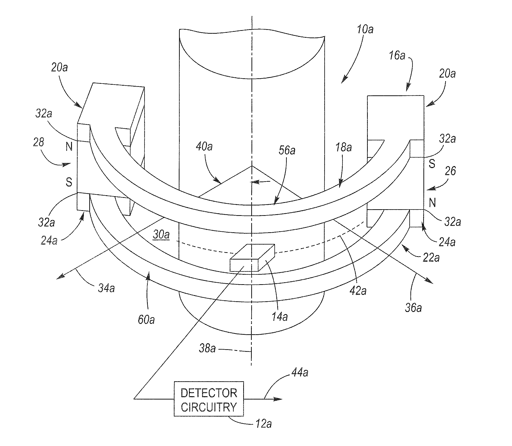
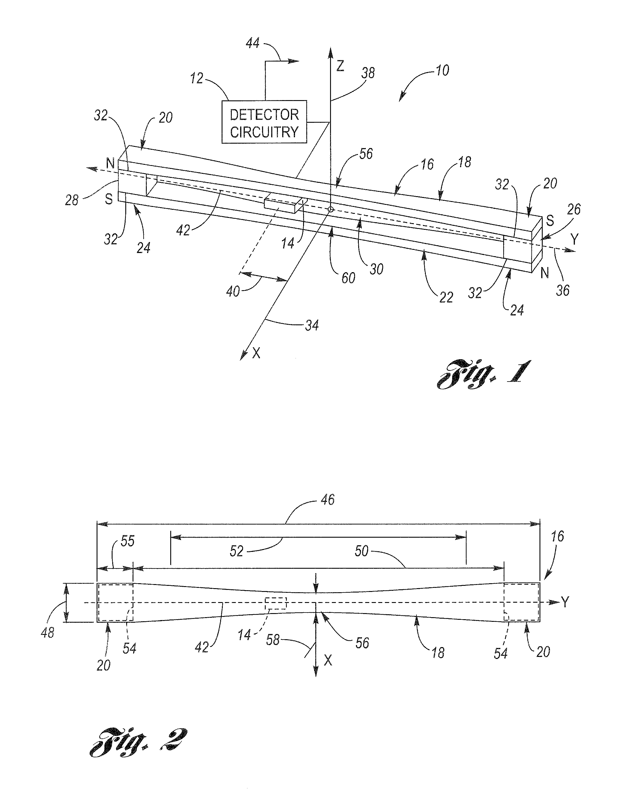
[0021]Referring now to the drawings wherein like reference numerals are used to identify identical components in the various views, FIG. 1 is a simplified isometric view of a linear position sensor 10 of the present invention. Sensor 10 is configured to cooperate with a detector circuit 12. The sensor 10 includes a galvanomagnetic sensing element 14 configured to sense the magnetic flux passing therethrough, and magnet / flux concentrator assembly 16. In general, the sensing element 14 and the magnet / flux concentrator assembly 16 are configured to move one with respect to the other. In the illustrated embodiment, however, sensing element 14 is stationary while assembly 16 is configured to be movable with respect to sensing element 14. It should be understood, however, that this configuration may be reversed such that the sensing element 14 is movable and the assembly 16 is stationary, with the same effect of one “moving” with respect to the other. Sensing element 14 may comprise conve...


PUM


Abstract

A non-contacting, magnet-based, rotary and linear travel absolute position sensor each include a stationary galvanomagnetic sensing element disposed in an air gap or slot of a movable magnet / flux concentrator assembly. The assembly has a first flux concentrator comprising ferromagnetic material having opposing magnet ends, and a second flux concentrator also comprising ferromagnetic material having opposing magnet ends but that is spaced apart from the first flux concentrator by a pair of magnets to form the air gap or slot. The magnet ends of each flux concentrator have a respective magnet area configured to engage a corresponding magnet and is configured in size and shape to cover the magnet. Additionally, the flux concentrators are configured in geometry to decrease in cross-sectional area from the inboard side of the magnet ends towards the center region of the concentrators, specifically the center of travel together provide improved linearity and signal to noise ratio of the output position signal.

Description

TECHNICAL FIELD[0001]The present invention relates generally to improvements in position sensors and more particularly to non-contacting rotary and linear travel sensors.BACKGROUND OF THE INVENTION[0002]Angular and linear absolute position sensors are widely used in automatic control systems as feedback-sensing devices in one or more control loops of the system. In the automotive industry, such position information may be used in substitution of more traditional, conventional control feedback provided by mechanical linkages, such as cables, rods, and the like.[0003]For example, in the automotive field, it may be desirable to know the linear absolute position of a long travel mechanism, such as a rack and pinion mechanism (i.e., that moves when a driver of an automotive vehicle turns the steering wheel), or the position of a sliding door on a minivan. In the first example, a linear absolute position sensor can provide information as to the linear position of the rack and pinion mecha...

Claims


Application Information

Patent Timeline
Patent Type & Authority Patents(United States)
IPC IPC(8): G01B7/30G01B7/14G01R33/07G01R33/09
CPCG01D5/145G01D2205/40G01D2205/775
Inventor MORENO, DANIEL J.LIN, YINGJIEMAXWELL, SUSAN A.
Owner DELPHI TECH INC
Why Eureka
Try Eureka