
Scanner with two sequential scan units

a scanning unit and scanning technology, applied in the field of laser light scanning, can solve the problems of requiring significant space for multiple lasers, affecting the resolution of multiple laser directions, and high cost of techniques, and achieve the effects of increasing lateral resolution, close monitoring, and improving the radiation angle of ligh

Inactive Publication Date: 2020-04-09
BLICKFELD GMBH
View PDF0 Cites 1 Cited by
  • Summary
  • Abstract
  • Description
  • Claims
  • Application Information

AI Technical Summary

Benefits of technology

This patent describes a scanning system that uses two mirrors to create a 2-D scan area for a detector. The two mirrors are mounted close to each other, which increases the detection aperture and allows for a high temporal resolution. The system also includes a magnet and an angular magnetic field sensor to monitor the rotation of the scanning unit, which improves lateral resolution. Overall, this patent describes a more efficient and accurate system for scanning in the LIDAR field.

Problems solved by technology

However, such techniques are expensive and require significant space for the multiple lasers.
In addition, a resolution along the direction of the plurality of lasers is typically comparatively limited: reference implementations have, for example, a resolution of between 4 and 64 dots in this direction.
In addition, with highly integrated reference implementations, it is often impossible, or only possible to a limited extent, to monitor the emission angle of the laser light.

Method used


Image

  • Scanner with two sequential scan units
  • Scanner with two sequential scan units
  • Scanner with two sequential scan units

Examples


example 1

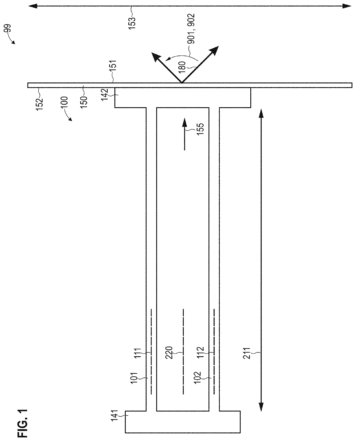
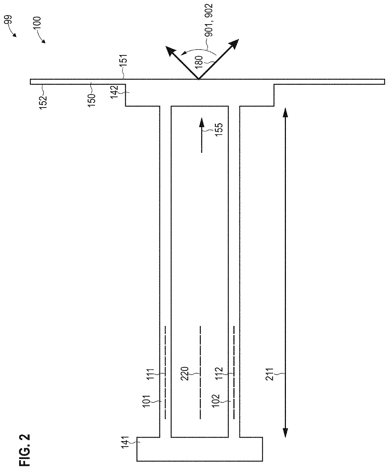
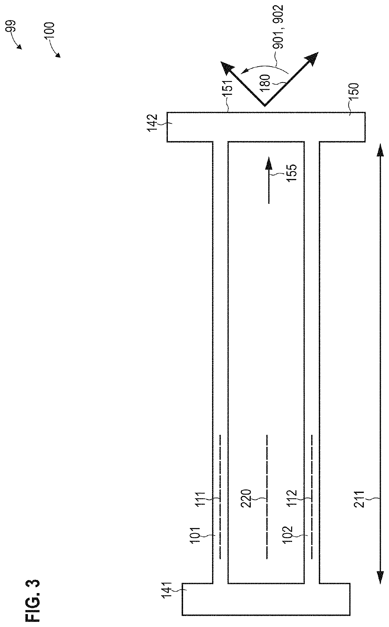
[0190]A scanner (90), comprising:[0191]a first mirror (150) having a reflective front side (151) and a rear side (152),[0192]a first elastic mounting (100) which extends and on a side facing the rear side (152) of the first mirror (150),[0193]a second mirror (150) having a reflective front side (151) and a rear side (152),[0194]a second elastic mounting (100) which extends on a side facing the rear side (152) of the second mirror (150),[0195]wherein the scanner (90) is configured to deflect light (180) sequentially at the front side (151) of the first mirror (150) and at the front side (151) of the second mirror (150).

example 2

[0196]The scanner (90) according to Example 1,[0197]wherein the first elastic mounting (100) comprises at least one elastic, rod-shaped element (101, 101-1, 101-2, 102, 102-1, 102-2), and / or[0198]wherein the second elastic mounting (100) comprises at least one elastic rod-shaped element (101, 101-1, 101-2, 102, 102-1, 102-2).

example 3

[0199]The scanner (90) according to Example 2,[0200]wherein a longitudinal axis (111, 112) of the at least one elastic rod-shaped element (101, 101-1, 101-2, 102, 102-1, 102-2) of the first elastic mounting (100) has an angle (159) of 45°±15° with a surface normal of the reflective front side (151) of the first mirror (150), and / or[0201]wherein a longitudinal axis (111, 112) of the at least one elastic rod-shaped element (101, 101-1, 101-2, 102, 102-1, 102-2) of the second elastic mounting (100) has an angle (159) of 45°±15° with a surface normal of the reflective front side (151) of the second mirror (150).


PUM


Abstract

A scanner (90) comprises a first mirror (150) having a reflective front side (151) and a rear side (152), a first elastic mounting (100) which extends on a side facing the rear side (152) of the first mirror (150), a second mirror (150) having a reflective front side (151) and a rear side (152), and a second elastic mounting (100) which extends on a side facing the rear side (152) of the second mirror (150). The scanner (90) is configured to deflect light (180) sequentially at the front side (151) of the first mirror (150) and at the front side (151) of the second mirror (150).

Description

TECHNICAL FIELD[0001]Various examples generally relate to a scanner for light. In particular, several examples relate to a laser light scanner that may be used, for example, for LIDAR measurements.BACKGROUND[0002]The distance measurement of objects is desirable in various fields of technology. For example, in the context of autonomous driving applications, it may be desirable to detect environmental objects of vehicles and, in particular, to determine a distance to the objects.[0003]One technique for measuring the distance of objects is the so-called LIDAR technology (light detection and ranging, sometimes also LADAR). For this purpose, for example, pulsed laser light is emitted by an emitter. The environmental objects reflect the laser light. These reflections can then be measured. By determining the transit time of the laser light, a distance to the objects can be determined.[0004]In order to detect the environmental objects spatially resolved, it may be possible to scan the laser...

Claims


Application Information

Patent Timeline
IPC IPC(8): G02B26/10G02B7/182G02B26/08G01S7/481G01S17/89G01S17/931
CPCG01S7/4817G02B26/0858G02B7/182G02B26/101G02B26/105G01S17/89G01S17/931
Inventor PETIT, FLORIANMUELLER, MATHIAS
Owner BLICKFELD GMBH
Learn More