
Adjustable antenna element and antennas employing same

a technology of adjustable antenna elements and antennas, which is applied in the direction of antennas, antenna feed intermediates, electrical devices, etc., can solve the problems of degrading the performance of the antenna, increasing the physical length of the antenna element, and increasing the complexity of the mechanical considerations for constructing such antennas

Active Publication Date: 2008-12-09
STEPPIR COMM SYST INC
View PDF26 Cites 10 Cited by
  • Summary
  • Abstract
  • Description
  • Claims
  • Application Information

AI Technical Summary

Benefits of technology

The solution allows for reduced antenna length, improved mechanical stability, and enhanced performance with lower impedance, achieving excellent frequency coverage and gain while maintaining a low voltage-standing-wave-ratio (VSWR).

Problems solved by technology

A limiting factor in prior-art antennas is that, as the frequency of operation of the antenna becomes lower, the physical length of the antenna element must increase to allow it to resonate at the selected frequency.
Of course, elements such as loading coils can be used to shorten the physical lengths of the antenna elements, but they degrade the performance of the antenna.
Mechanical considerations for constructing such antennas become more complicated as the element lengths increase as the operating frequency decreases.
Considerations such as mechanical stress and wind survivability make the design of such adjustable antenna systems more challenging when long element lengths are necessary.

Method used


Image

  • Adjustable antenna element and antennas employing same
  • Adjustable antenna element and antennas employing same
  • Adjustable antenna element and antennas employing same

Examples


Embodiment Construction

[0025]Those of ordinary skill in the art will realize that the following description of the present invention is illustrative only and not in any way limiting. Other embodiments of the invention will readily suggest themselves to such skilled persons.

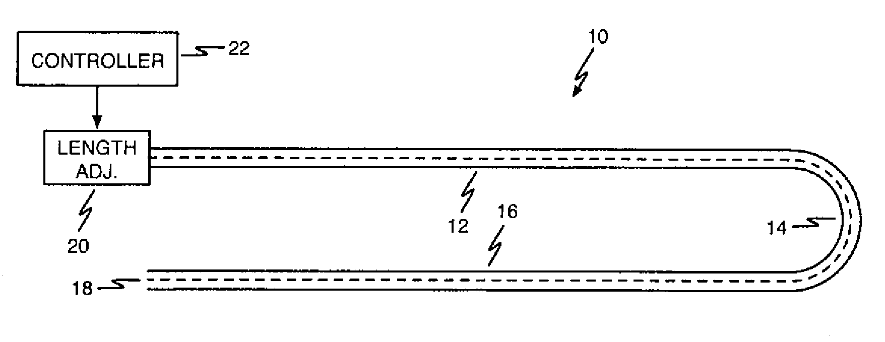
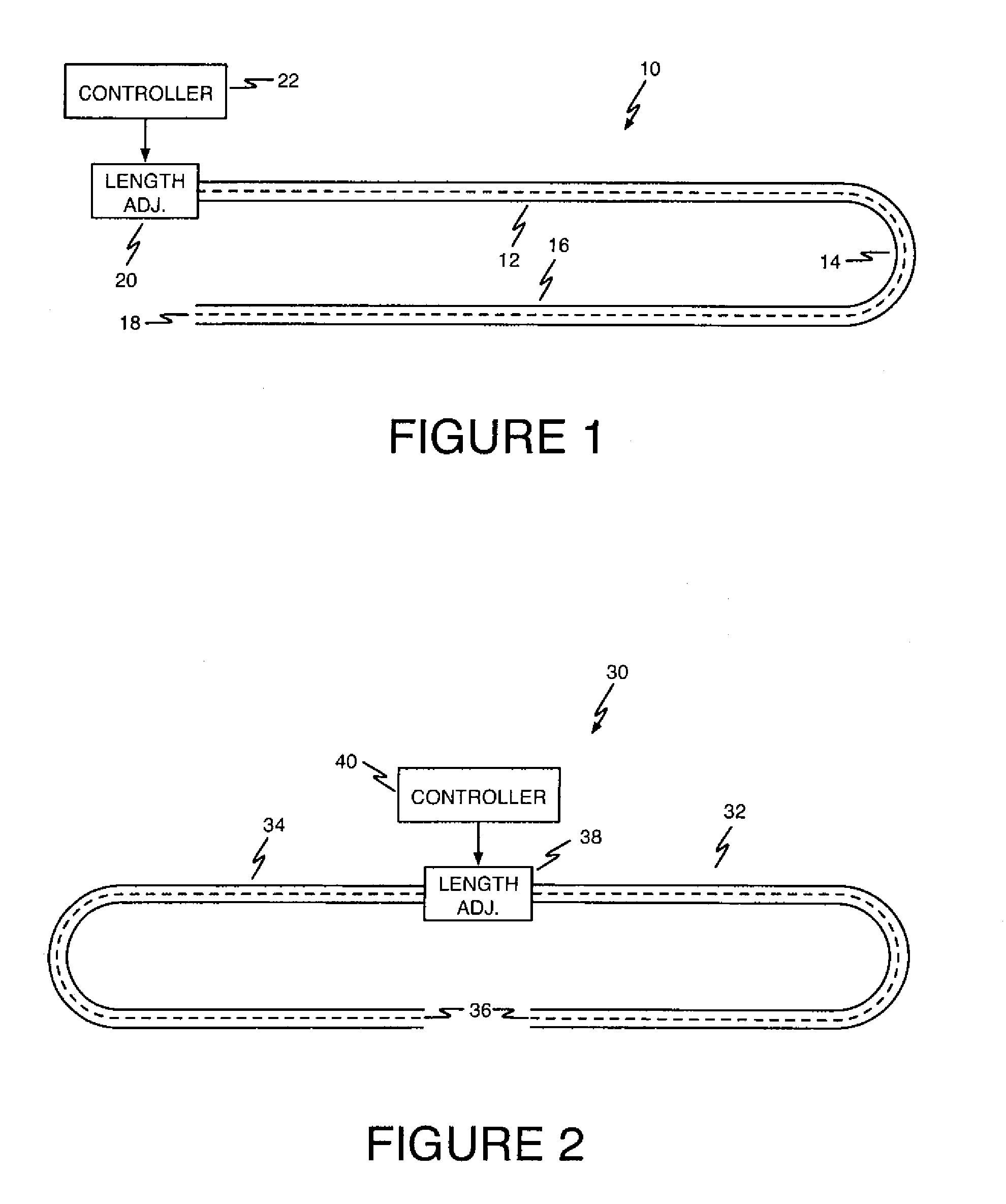
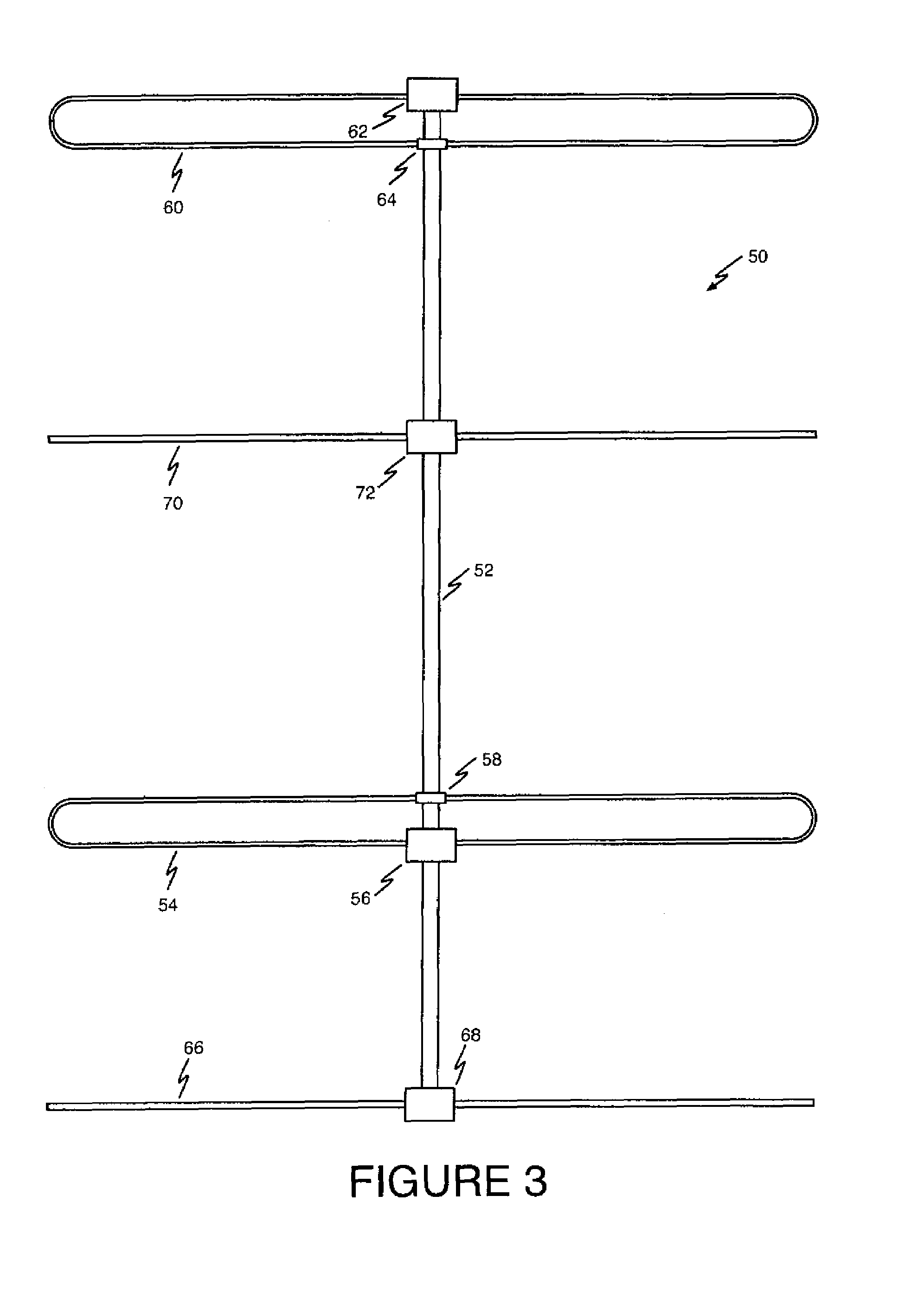
[0026]Referring first to FIG. 1, an illustrative antenna element 10 according to the present invention includes a hollow support arm including a first section 10, a curved transition section 14, and a second section 16. While it is presently preferred that first and second sections 12 and 16 be substantially straight, this is not a requirement. The hollow support arm is formed from a non-conductive material such as fiberglass.

[0027]The loop element is mechanically a more complex element than a straight element is and is subject to torques imparted by wind forces that can distort, bend, or kink the return loop. To prevent this would require the loop to be made of a suitable material such as fiberglass or something at least that strong. F...


PUM


Abstract

An antenna system with at least one tunable dipole element with a length adjustable conductive member disposed. The element is made of two longitudinally aligned, hollow support arms made of non-conductive material. Disposed longitudinally inside each element is a length adjustable conductive member electrically connected at one end. Each conductive member is stored on a spool that is selectively rotated to extend the conductive member into the support arm. The support arms are affixed at one end to a rigid housing. During use, the conductive members are adjusted in length to tune the element to a desired frequency. The antenna can be optimally tuned at a specific frequency for maximum gain, maximum front-to-back ratio, as a bi-directional antenna, and to provide a desired feed point impedance. An electronic control system allows the length of the conductive members to be manually or automatically adjusted to a desired frequency.

Description

CROSS-REFERENCE TO RELATED APPLICATIONS[0001]This application claims benefit of U.S. Provisional Patent Application Ser. No. 60 / 743,874, filed Mar. 28, 2006, the entirety of which is incorporated by reference herein.BACKGROUND[0002]1. Technical Field[0003]The present invention relates to the field of radio antennas, and to wide frequency coverage vertical, dipole and parasitic array antennas. More particularly, the present invention relates to an adjustable antenna element, and to antenna systems employing one or more such adjustable elements.[0004]2. Description of the Prior Art[0005]Antenna systems employing a single antenna having adjustable-length elements providing excellent performance over a wide frequency range are known in the art. Examples of such antenna systems are the antenna systems manufactured and sold by Steppir Antennas of Issaquah, Wash., and include dipole, vertical, and yagi antennas.[0006]A limiting factor in prior-art antennas is that, as the frequency of oper...

Claims


Application Information

Patent Timeline
Patent Type & Authority Patents(United States)
IPC IPC(8): H01Q21/12
CPCH01Q3/12H01Q9/16H01Q9/26H01Q19/30
Inventor MERTEL, MICHAEL E.CURTISS, CLAYTON BTHOMAS, JAMES E.
Owner STEPPIR COMM SYST INC
Learn More