Method and apparatus for circulatory valve repair

a technology of circulatory valve and repair method, which is applied in the field of repair of heart valves, can solve the problems of significant postoperative left ventricular dysfunction, deteriorating ventricular performance, and patients in the early or late stages of the disease are not considered suitable candidates, so as to reduce or eliminate mitral regurgitation, increase efficiency, and reduce the effect of mitral regurgitation

Inactive Publication Date: 2008-12-16
THE TRUSTEES OF COLUMBIA UNIV IN THE CITY OF NEW YORK
View PDF232 Cites 237 Cited by
  • Summary
  • Abstract
  • Description
  • Claims
  • Application Information

AI Technical Summary

Benefits of technology

[0013]It is an object of the invention to provide a method for the repair of heart valves to increase their efficiency.
[0015]It is also an object of the invention to provide for a method for the repair of the mitral valves which eliminates the need for cardiopulmonary bypass surgery.
[0017]It is a yet further object of the invention to provide for the repair of a mitral valve by percutaneous insertion of a grasping and fastening device into the heart to repair a mitral valve and reduce or eliminate mitral regurgitation.

Problems solved by technology

Consequently, some patients in the early or late stages of the disease are not considered appropriate candidates due to the high risk associated with the operation.
Multiple studies have demonstrated that prosthetic replacement of the mitral valve can lead to significant postoperative left ventricular dysfunction and often requires lifelong treatment with anticoagulants.
Nevertheless, recent studies performed by the inventors (Umana et al., Surg Forum 1997) have revealed that posterior ring annuloplasty causes changes in ventricular geometry that lead to paradoxical movement of the normal papillary muscles, further deteriorating ventricular performance.
The system has inherent limitations in terms of its effectiveness for the procedure described and its applicability, if any, to other valves, especially cardiac valves.

Method used


Image

  • Method and apparatus for circulatory valve repair
  • Method and apparatus for circulatory valve repair
  • Method and apparatus for circulatory valve repair

Examples


Embodiment Construction

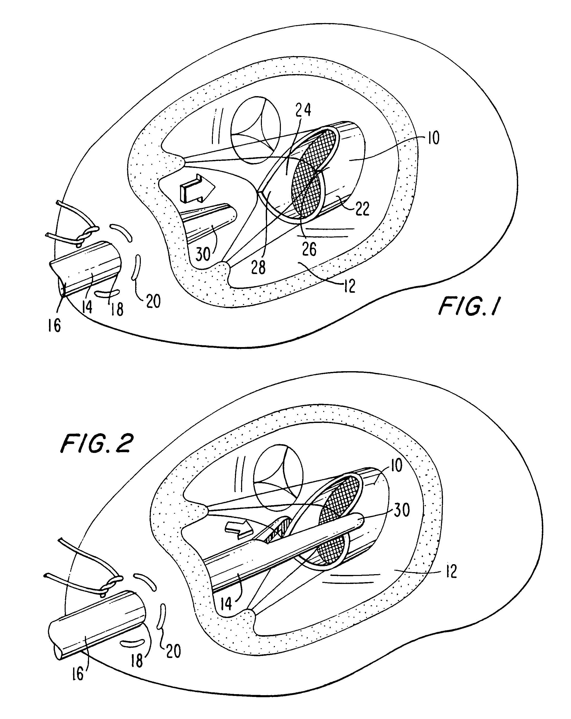
[0040]The invention can perhaps be better appreciated by making reference to the drawings. In FIG. 1 a portion of the human heart is depicted showing a mitral valve 10, a left ventricle 12 and the distal end 14 of a grasper apparatus of the invention 16, which has been inserted through an incision 18 in left ventricle 12. Incision 18 is loosely sutured with sutures 20 to loosely hold distal end 18 and to prevent bleeding.

[0041]Mitral valve 10 comprises anterior leaflet or cusp 22 and posterior leaflet or cusp 24, as well as two commissural cusps (not shown). The primary intent of the invention herein is to secure the distal sections 26 and 28 of cusps 22 and 24, respectively, together or substantially adjacent.

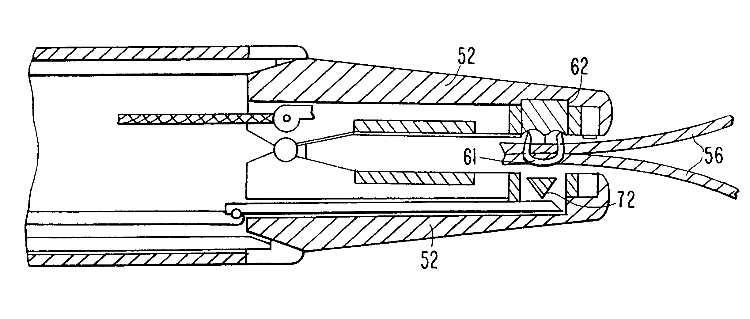
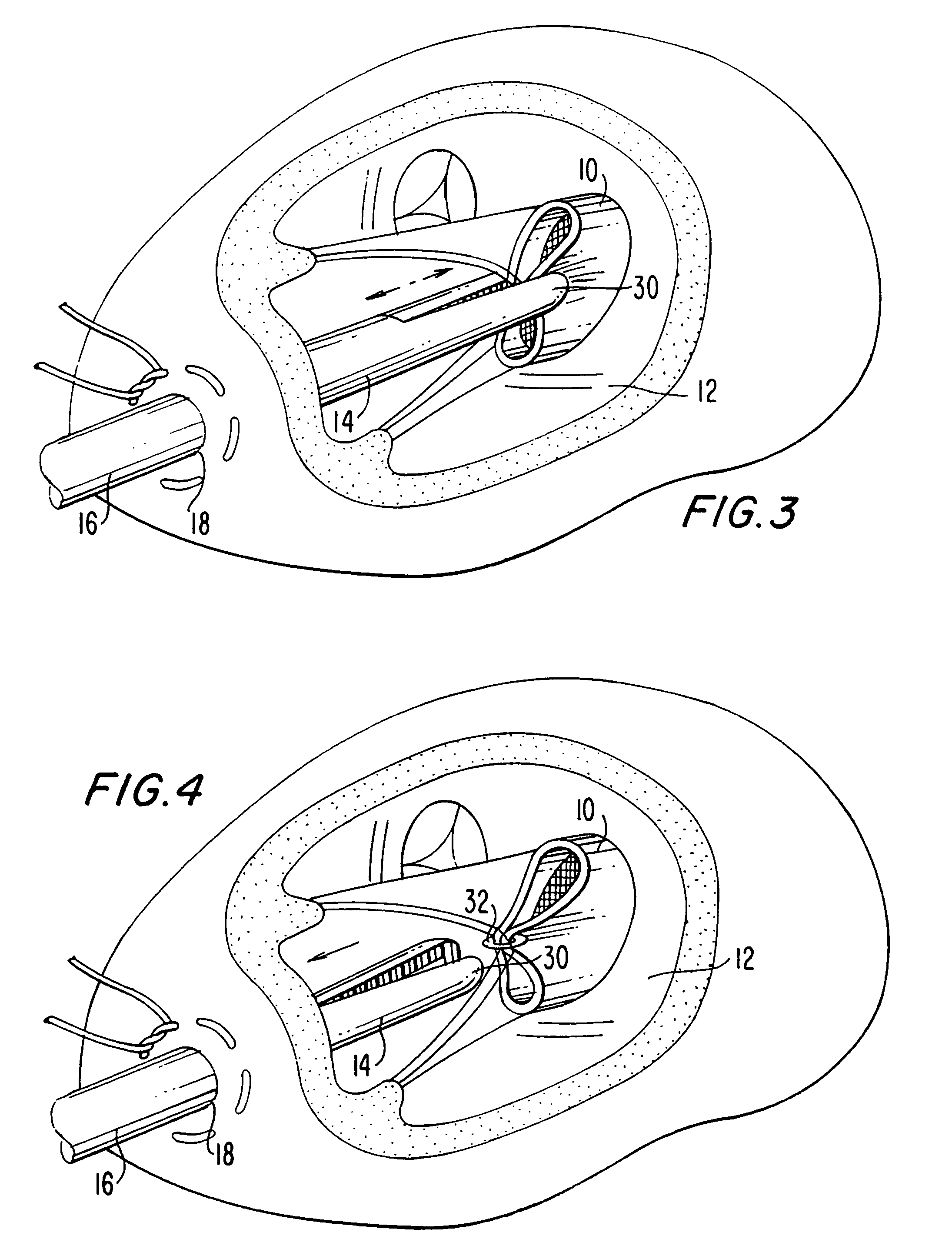
[0042]As can be seen in FIG. 2, the jaws 30 of distal end 14 are separated and positioned exterior to cusps 22 and 24. Then, as shown in FIG. 3, jaws 30 are clamped together to cause cusp distal sections 26 and 28 to come together. Once a closure is embedded, such as the loop ...


PUM


Abstract

An apparatus for the repair of a cardiovascular valve has leaflets comprising a grasper capable of grabbing and co-apting the leaflets of the valve. In a preferred embodiment the grasper has jaws that grasp and immobilize the leaflets, and then a fastener is inserted to co-apt the leaflets. The apparatus is particularly useful for repairing mitral valves to cure mitral regurgitation.

Description

CROSS-REFERENCE TO RELATED APPLICATIONS[0001]This application is a divisional of co-pending, commonly assigned U.S. patent application Ser. No. 09 / 950,163, filed Oct. 15, 2002, which is a continuation of commonly assigned U.S. patent application Ser. No. 09 / 747,558, filed Dec. 23, 2000, now abandoned, which is a continuation of commonly assigned U.S. patent application Ser. No. 09 / 254,111, filed Feb. 25, 1999, now U.S. Pat. No. 6,269,819, which is a National Phase of commonly assigned PCT Patent Application No. PCT / US98 / 13240, filed Jun. 25, 1998, which corresponds to U.S. Provisional Patent Application Ser. No. 60 / 051,078, filed Jun. 27, 1997, now abandoned.FIELD OF THE INVENTION[0002]The present invention relates generally to the field of circulatory valve repair. More particularly, the present invention relates to the field of the repair of heart valves and specifically for the repair of mitral heart valves, for patients suffering from mitral regurgitation.BACKGROUND OF THE INVEN...

Claims


Application Information

Patent Timeline
Patent Type & Authority Patents(United States)
IPC IPC(8): A61B19/00A61B17/08A61B17/10A61B17/00A61B17/12A61B17/03A61B17/04A61B17/064A61B17/122A61B17/128A61F2/24
CPCA61B17/064A61B17/0644A61B17/08A61B17/10A61B17/0686A61B17/1285A61B17/122A61B2017/00243A61B2017/0649A61F2/2427
Inventor OZ, MEHMET C.LEMOLE, GERALD M.LOTVIN, ALANUMANA, JUAN P.ALLENLEVIN, HOWARD R.
Owner THE TRUSTEES OF COLUMBIA UNIV IN THE CITY OF NEW YORK
Why Eureka
Try Eureka