Eureka AIR delivers breakthrough ideas for toughest innovation challenges, trusted by R&D personnel around the world.

Object based boundary refinement method

a boundary refinement and object technology, applied in image enhancement, image analysis, instruments, etc., can solve the problems of difficult to specify what constitutes an object of interest in an image, difficult to enforce the above rules, and erroneous analysis and conclusions drawn based on incorrect measurements. achieve the effect of simple initial detection, high-quality object segmentation masks, and fast processing

Active Publication Date: 2008-12-16
LEICA MICROSYSTEMS CMS GMBH
View PDF13 Cites 17 Cited by
  • Summary
  • Abstract
  • Description
  • Claims
  • Application Information

AI Technical Summary

Benefits of technology

The patent describes a method for improving the accuracy of object segmentation in digital images. It uses an initial object region of interest to define refinement zones and performs directional edge enhancement to improve the contrast of the image. The method also detects the edges of the image and performs final shaping to create a single object region output. The technical effect of this method is to improve the accuracy and reliability of object segmentation in digital images.

Problems solved by technology

The measurements performed on the segmented objects will certainly be incorrect and therefore any analysis and conclusion drawn based on the incorrect measurements will be erroneous and compromised.
It is difficult to specify what constitutes an object of interest in an image and define the specific segmentation procedures.
However, enforcing the above rules is difficult because strictly uniform and homogeneous regions are typically full of small holes and have ragged boundaries.
Insisting that adjacent regions have large differences in values could cause regions to merge and boundaries to be lost.
Therefore, it is not possible to create a universal object segmentation method that will work on all types of objects in real life situations.
They are therefore limited to standard assays and are non-robust and inflexible for changes.
High content / context screening assays provide large amounts of biological and chemical information that could help researchers discover the most effective drugs more efficiently, while getting flawed compounds to “fail fast,” thus saving considerable time and expense.
However, in the live cell assay, in order to maintain the cell nature environment for meaningful studies there is limited control over the staining quality and cell configuration arrangement.
This represents a formidable challenge for fully automatic cell segmentation.
However, the resulting object regions are often not accurate.
Alternative methods of object segmentation is boundary based method (C. C. Leung, W. F. Chen2, P. C. K. Kwok, and F. H. Y. Chan, Brain Tumor Boundary Detection in MR Image with Generalized Fuzzy Operator, IEEE International Conference on Image Processing, September 2003.) which could yield accurate object boundary but often have gaps between the edges and cannot completely define an object region, problem in object connectivity.
Any analysis and conclusion drawn based on the incorrect measurements will be erroneous and compromised.
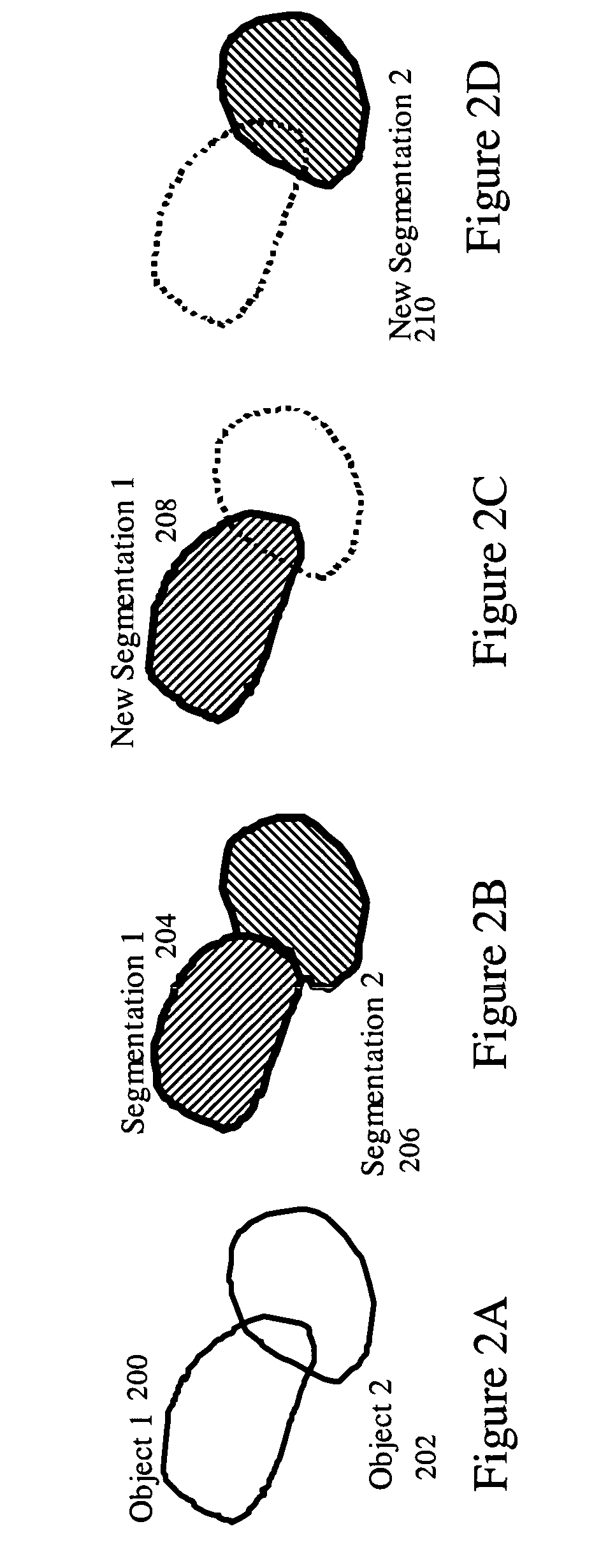
It fails when the boundary of an object is shared by other objects due to touching or overlapping.
This limitation presents a significant disadvantage that hinders quantitative analysis and automation.

Method used


Image

  • Object based boundary refinement method
  • Object based boundary refinement method
  • Object based boundary refinement method

Examples


Embodiment Construction

I. Application Scenario

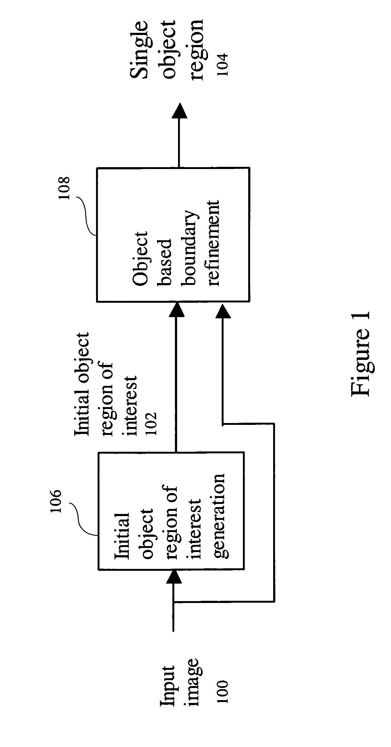
[0033]The processing flow for the application scenario of the object based boundary refinement method is shown in FIG. 1. It includes two steps. The first step, initial object region of interest generation 106, generates a single initial object region of interest 102 from the input image 100. The second step, object based boundary refinement 108, performs one object of interest boundary refinement within the single initial object region of interest 102. This results in single object region 104 output.

[0034]As shown in FIG. 1, the input image 100 is processed by the initial object region of interest generation 106 step for single initial object region of interest 102 generation. The single initial object region of interest 102 could be generated automatically using methods such as initial detection followed by region partition (Shih-Jong J. Lee, Tuan Phan, “Method for Adaptive Image Region Partition and Morphologic Processing”, U.S. patent application Ser. No. ...


PUM


Abstract

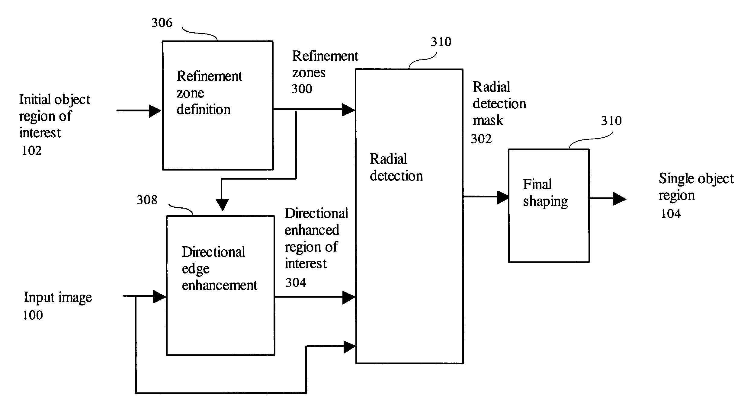
An object based boundary refinement method for object segmentation in digital images receives an image and a single initial object region of interest and performs refinement zone definition using the initial object regions of interest to generate refinement zones output. A directional edge enhancement is performed using the input image and the refinement zones to generate directional enhanced region of interest output. A radial detection is performed using the input image the refinement zones and the directional enhanced region of interest to generate radial detection mask output. In addition, a final shaping is performed using the radial detection mask having single object region output.A directional edge enhancement method determining pixel specific edge contrast enhancement direction according to the object structure direction near the pixel consists receives an image and refinement zones and performs 1D horizontal distance transform and 1D vertical distance transform using the refinement zones to generate horizontal distance map and vertical distance map outputs. A neighboring direction determination is performed using the horizontal distance map and the vertical distance map to generate neighboring image output. In addition, a directional edge contrast calculation using the neighboring image and input image having directional enhanced region of interest output.

Description

TECHNICAL FIELD[0001]This invention relates to the enhanced segmentation of digital images containing objects of interest to determine the regions in the images corresponding to those objects of interest.BACKGROUND OF THE INVENTION[0002]Image object segmentation processes digital images containing objects of interest and determines the regions in the images corresponding to those objects of interest. Image object segmentation is critical for many applications such as the detection of the coronary border in angiograms, multiple sclerosis lesion quantification, surgery simulations, surgical planning, measuring tumor volume and its response to therapy, functional mapping, automated classification of blood cells, studying brain development, detection of microcalcifications on mammograms, image registration, atlas-matching, heart image extraction from cardiac cineangiograms, detection of tumors, cell high content screening, automatic cancer cell detection, semiconductor wafer inspection,...

Claims


Application Information

Patent Timeline
Patent Type & Authority Patents(United States)
IPC IPC(8): G06K9/40G06K9/42G06K9/44G06V10/26
CPCG06K9/0014G06K9/34G06T7/0012G06T7/0083G06T7/0091G06T2207/20104G06T2207/20192G06T2207/30024G06T7/12G06T7/155G06V20/695G06V10/26
Inventor OH, SEHOLEE, SHIH-JONG J.
Owner LEICA MICROSYSTEMS CMS GMBH
Why Eureka
Eureka Blog
Learn More