Magnetic device

a magnetic device and magnetic field technology, applied in the direction of transformer/inductance cooling, printed circuit aspects, coils, etc., can solve the problems of only effective heat removal, marginal improvement in heat transfer, and limiting factors in the design and application of such transformers, so as to avoid high temperature gradients, reduce heat loss, and reduce heat loss

Active Publication Date: 2008-12-23
DET INT HLDG LTD
View PDF11 Cites 10 Cited by
  • Summary
  • Abstract
  • Description
  • Claims
  • Application Information

AI Technical Summary

Benefits of technology

[0009]It is the object of the invention to create a magnetic device pertaining to the technical field initially mentioned, that is inexpensive, allows for efficient heat removal, avoids high temperature gradients and adds no extra inductance or resistance.

Problems solved by technology

One of the limiting factors in the design and application of such transformers is heat removal.
In many cases the amount of power that can be processed through a transformer is purely dependent upon the thermal limitations imposed by the transformer.
Often, a physically larger transformer is used purely because it can dissipate more heat than a smaller one due to its larger surface area, despite the fact that the larger transformer generates more losses than the smaller one.
Apart from the extra expense involved, the improvement in heat transfer is marginal.
However, the removal of heat is only effective in local areas surrounding the places of attachment of the posts.
The posts add unwanted inductance and resistance and increase the total assembly height.

Method used


Image

  • Magnetic device
  • Magnetic device
  • Magnetic device

Examples


Embodiment Construction

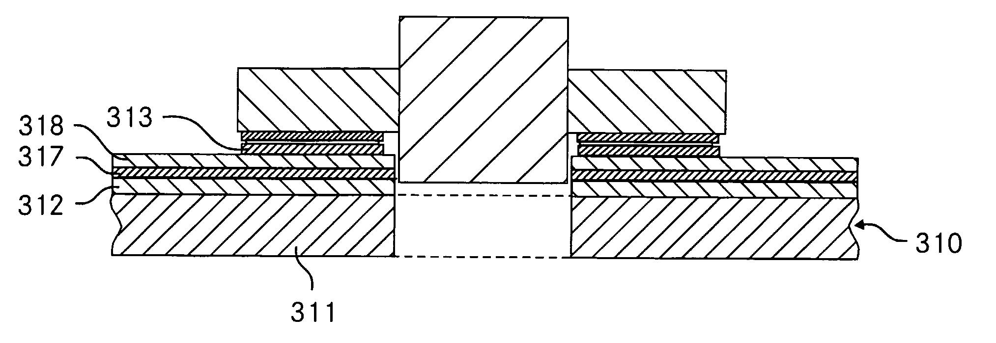
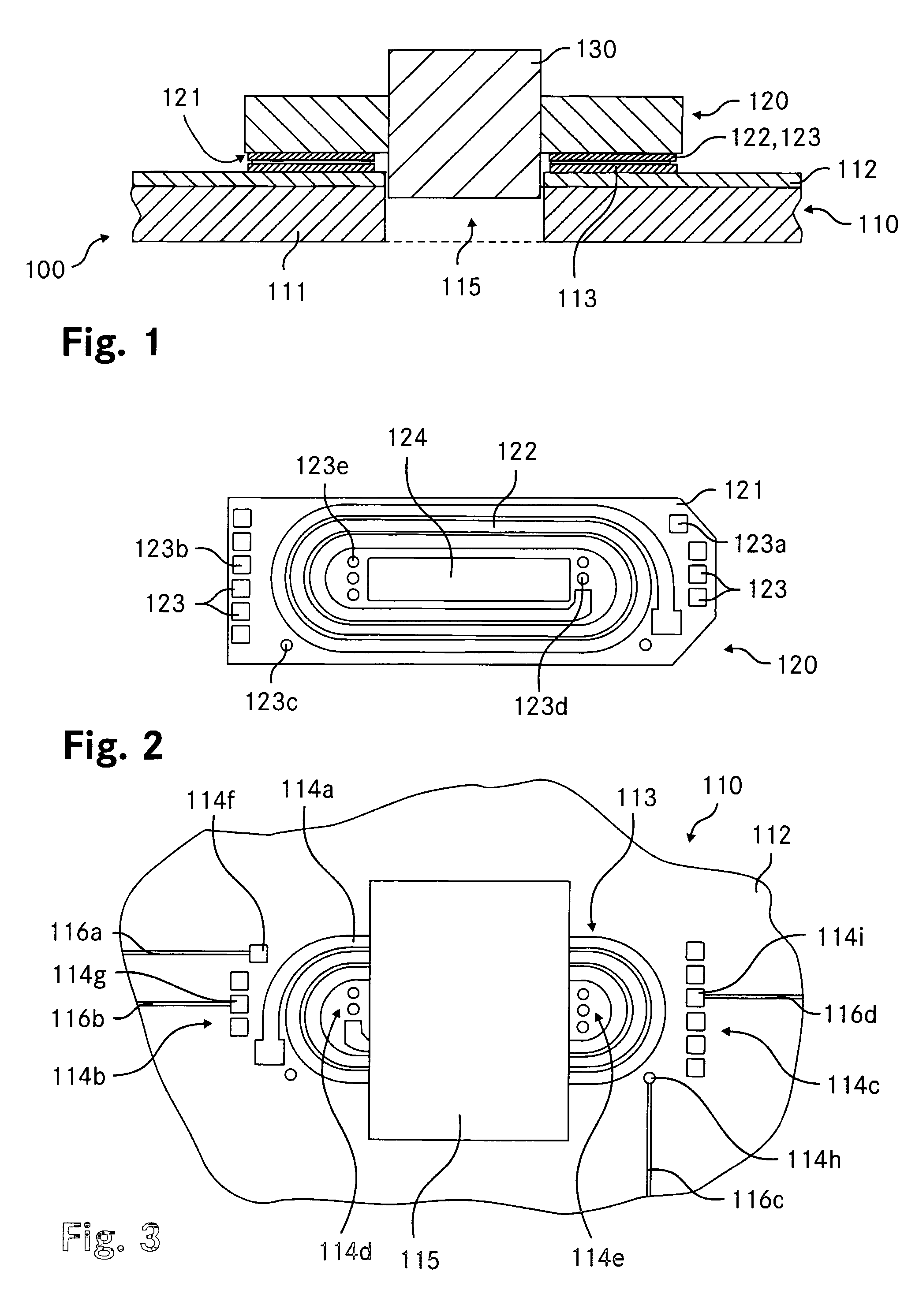
[0036]The FIGS. 1-3 show schematic representations of an inventive transformer arrangement. The FIG. 1 is a cross-sectional view along a vertical plane running through the principal axis of the transformer windings. The FIG. 2 is a plan view of the solderside of the circuit board carrying the windings. The FIG. 3 is a plan view of the upper side of the motherboard.

[0037]The transformer arrangement 100 is constituted by the motherboard 110, the additional circuit board 120 carrying the windings and the magnetic core 130 surrounding and passing through the circuit board 120. The motherboard 110 is an insulated metal surface board (IMS) composed of three layers. The metallic base layer 111, which usually is the thickest of the IMS layers, consists of aluminum. The insulating layer 112 covering the base layer 111 is made of a plastic material, e.g. of F24 which is a commonly used dielectric substrate material in circuit board design. The top layer 113 is constituted by a thin copper foi...


PUM

PropertyMeasurementUnit
thermally conductiveaaaaaaaaaa
magneticaaaaaaaaaa
conductiveaaaaaaaaaa

Abstract

A magnetic device to be surface mounted on a substantially planar thermally conductive surface comprises a circuit board containing a winding pattern having at least one winding and a magnetic core that is at least partially encompassing the winding pattern. On a bottom side of the circuit board a region corresponding to a substantial part of the winding pattern is covered by a thermally conductive material for thermally contacting the thermally conductive surface. A transformer arrangement comprises such a magnetic device as well as a thermally clad circuit board having a surface area covered by a thermally conductive material, corresponding to at least substantially the covered region on the bottom side of the circuit board. For assembly, the covered region on the bottom side of the circuit board is soldered to the covered region on the surface of the thermally clad circuit board. The extensive cover and thermal contact to the thermally conductive surface allows for heat transfer from the complete winding area, reducing the total thermal resistance and temperature gradients in the winding structure. The solution is inexpensive and easy to manufacture.

Description

CROSS REFERENCE TO RELATED APPLICATIONS[0001]This application is the National Stage application of the Patent Cooperation Treaty Application No. PCT / CH2004 / 000141, from which priority is claimed.TECHNICAL FIELD[0002]The invention relates to a magnetic device to be surface mounted on a substantially planar thermally conductive surface, comprising a circuit board containing a winding pattern having at least one winding and a magnetic core at least partially encompassing the winding pattern. The invention further relates to a transformer arrangement comprising the magnetic device.BACKGROUND ART[0003]Power supplies often substantially determine the size of electronic circuits or devices. Due to this reason, compact and highly efficient planar transformers have been developed.[0004]For example, the U.S. Pat. No. 6,069,548 (Nokia) discloses a planar transformer constituted by a supplementary circuit board surrounded by a magnetic core. The planar transformer is conventionally surface moun...

Claims


Application Information

Patent Timeline
Patent Type & Authority Patents(United States)
IPC IPC(8): H01F5/00H01F27/22H01F27/28H05K1/02H05K1/05H05K1/14H05K1/16H05K1/18H05K3/34
CPCH01F27/22H01F27/2804H05K1/165H05K1/0203H05K1/021H05K1/056H05K1/141H05K1/182H05K3/341H05K2201/086H05K2201/09063H05K2201/09781
Inventor SPRINGETT, NIGEL
Owner DET INT HLDG LTD
Why Eureka
Try Eureka