

Submersible tethered platform for undersea electrical power generation
a technology of electrical power generation and submerged platforms, which is applied in water-power plants, mechanical equipment, machines/engines, etc., can solve the problems of seabed emplacement (without vertical operational positionability), severe disruption to shipping, surface transportation, fisheries, aesthetics, etc., and achieve the effect of adequate separation
- Summary
- Abstract
- Description
- Claims
- Application Information
AI Technical Summary
Benefits of technology
Problems solved by technology
Method used
Image

Examples
Embodiment Construction
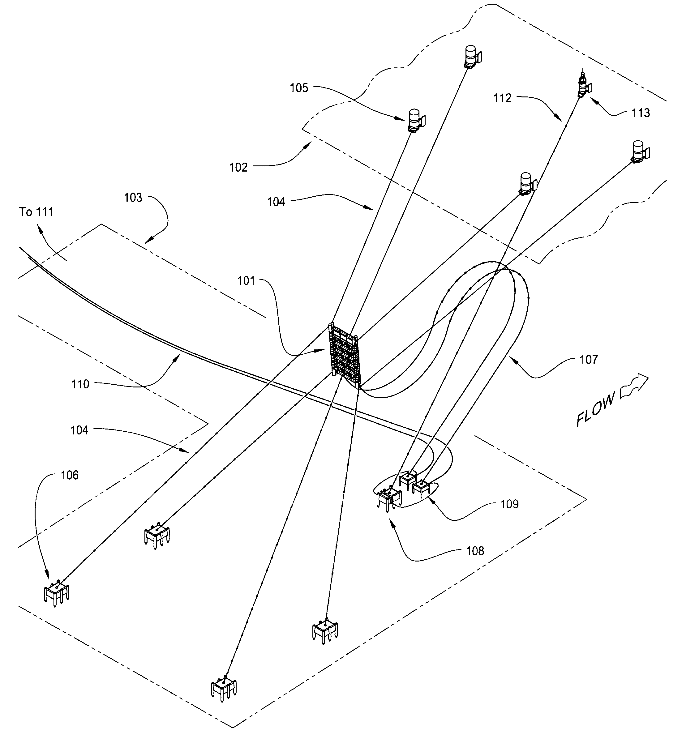
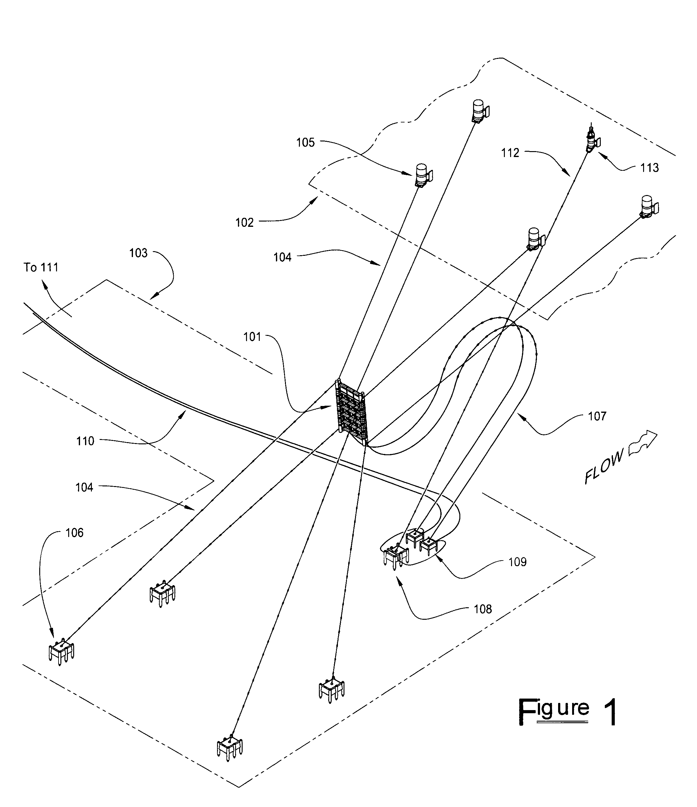
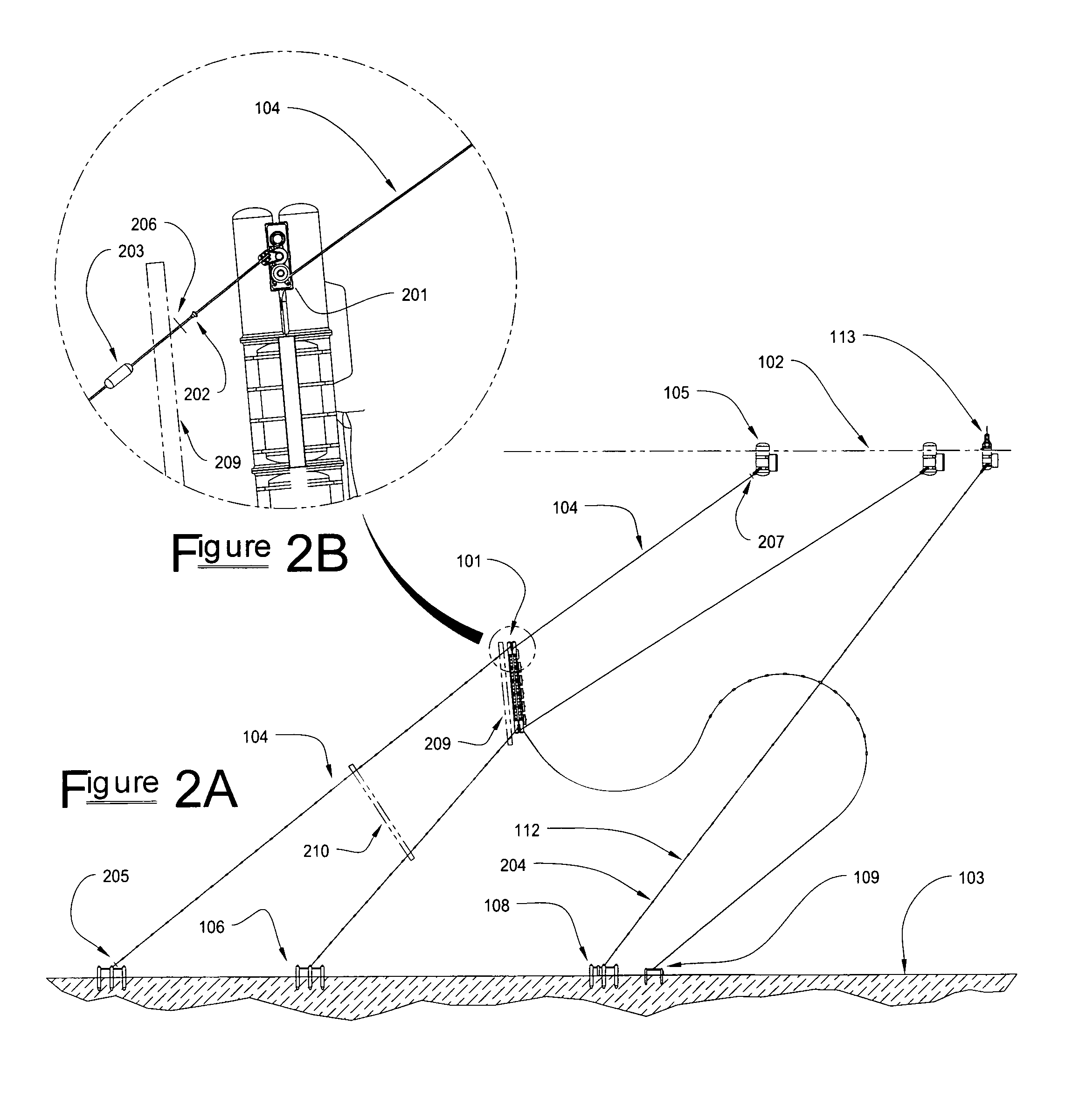
[0065]Referring first to FIG. 1 the overall invention, involving the submersible platform 101 proper and its adjunct equipment, is depicted in a preferred embodiment and exemplary operational deployment. The platform is shown suspended in the water column, that is, between the ocean surface 102 and floor 103. The platform is retained against and normal to the flow of ocean current by means of flexible tension members (i.e., mooring lines) 104. The free end of each said mooring line is shown retained at the surface by means of a mooring line buoy 105, with the fixed end secured to the ocean floor by means of an anchor 106. The platform resides at a predetermined operational depth and angular attitude, in relationship to the ocean current, such depth and attitude having been selected for reasons of optimal current engagement, adequate distance from surface turbulence, proximity to any further application-specific ancillary equipment (not illustrated) on the seabed, etc. Having its win...
PUM
 Abstract
Description
Claims
Application Information